Operation
11
3.5
Feature Description
3.5.1 Micro-Adjustment
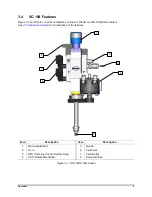
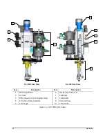
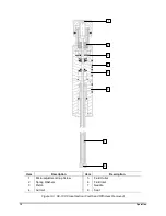
The piston and needle travel is adjusted by rotating the micro-adjustment cap screw at the top of the film
coater. Rotating the micro-adjustment cap clockwise decreases the piston and needle travel, decreasing
the amount of coating material allowed to flow through the seat. Rotating the micro-adjustment cap
counterclockwise increases the piston and needle travel, increasing coating material flow.
3.5.2 Air Inlet
Trigger air enters the film coater from the solenoid valve on the manifold; through the air inlet. The trigger
air then travels upward through the bore and presses against the piston. Air pressure forces the piston
upward to overcome the downward pressure exerted by the spring washers. A seal on the piston and an
O-ring on the piston retainer help prevent trigger air from leaking past the piston. Any air that does leak
past the piston is vented through the weep hole in the side of the film coater cap.
3.5.3 0-90° Rotate Mechanism (Fourth Axis)
A rotary air cylinder activates, causing the extension and nozzle to rotate 90º. When the rotary cylinder air
is exhausted, the extension and nozzle are rotated back to the original position.
3.5.4 Rotate and Tilt Mechanism (Fifth Axis)
The tilt mechanism is available on the SC-105HS Film Coater only. Two rotary cylinders are coupled
together to provide four 90° indexed positions. Air activates a cylinder located on the manifold, causing
the tilt mechanism to activate. The cylinder arm extends or retracts, moving a sleeve on the extension up
or down. This motion is transferred to the tilt lever, which tilts the nozzle from 0° to 30°.
3.5.5 Piston and Needle
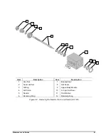
The piston is forced upward by the trigger air until it comes in contact with the micro-adjustment cap
screw. The needle attached to the piston pulls away from the seat, which allows coating material to flow
through the opening in the seat. Air that may leak past the hat seals is vented out the weep hole in the
upper-body module (between the hat seals and the U-cap seal).
3.5.6 Fluid
Pressurized coating material enters the lower-body module through the fluid inlet, flows into the extension
through the seat and out through the nozzle. Unused coating material flows through a bore in the center
of the needle into the upper-body module to the fluid outlet.
3.5.7 Solenoid Valve
A normally closed air solenoid valve is mounted on the film coater manifold. When 24 Vdc is supplied to
the valve, it opens, allowing air in to trigger the gun. Mounting the solenoid valve directly on the manifold
provides a quick response time for short-duration dispense operations.
3.5.8 Mounting
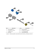
A mounting block and manifold mounts the film coater on the head of the gantry robot. Locating holes are
provided for positioning the film coater. Two #8-32 (C-74X) or two M4 x.7 (SL-94XE) machine screws
secure the film coater to the robot.

