background image

ASUS PRIME Q370M-C

1-1

Product introduction

1

Motherboard overview

• 

Unplug the power cord from the wall socket before touching any component.

• 

Before handling components, use a grounded wrist strap or touch a safely grounded 

object or a metal object, such as the power supply case, to avoid damaging them due 

to static electricity.

• 

Before you install or remove any component, ensure that the ATX power supply is 

switched off or the power cord is detached from the power supply. Failure to do so 

may cause severe damage to the motherboard, peripherals, or components.

• 

Unplug the power cord before installing or removing the motherboard. Failure to do so 

can cause you physical injury and damage to motherboard components.

Place this 

side towards 

the rear of the 

chassis

Scan the QR code to get the detailed pin definitions.

PCI

PCIEX1_1

PCIEX1_2

SPEAKER

CHASSIS

DIS_ME

CLRTC

F_PANEL

LPC_DEBUG

LPT

U31G1_56

U31G1_78

AAFP

MONO_OUT

EATX12V

EATXPWR

CHA_FAN2

CPU_FAN

CHA_FAN1

BATTERY

PCIEX16

Super

I/O

ASM

1083

ALC

887

DIGI

+VRM

24.4cm(9.6in)

24.4cm(9.6in)

LGA1151

Intel

®

Q370

Intel

®

I219LM

DDR4 DIMM_B1 (64bit, 288-pin module)

2280

2260

2242

2280

2260

2242

M.2_2(SOCKET3)

M.2_2(SOCKET3)

PCIE SATA IRST

X4

X

V

M.2_1(SOCKET3)

PCIE SATA IRST

X4

V

V

M.2_1(SOCKET3)

DDR4 DIMM_B2* (64bit,288-pin module)

DDR4 DIMM_A1 (64bit, 288-pin module)

DDR4 DIMM_A2* (64bit, 288-pin module)

AUDIO

KBMS

DP12

LAN_USB56

U31G2_12

U31G2_34

128Mb

BIOS

64Mb

BIOS

SATA6G_4

SATA6G_3

SATA6G_6 SATA6G_5

SATA6G_2

SATA6G_1

HDMI

VGA

USB1112

COM1

COM2

M.2(WIFI)

1

4

3

2

5

1

1

8

10 9

12 11

2

7

1

7

14

15

20

6

6

3

16

17

13

19

18

21

Содержание PRIME Q370M-C

Страница 1: ...Motherboard PRIME Q370M C PRIME Q370M C CSM ...

Страница 2: ...pective companies and are used only for identification or explanation and to the owners benefit without intent to infringe Offer to Provide Source Code of Certain Software This product contains copyrighted software that is licensed under the General Public License GPL under the Lesser General Public License Version LGPL and or other Free Open Source Software Licenses Such software in this product ...

Страница 3: ...0M C specifications summary vi Chapter 1 Product introduction Motherboard overview 1 1 Central Processing Unit CPU 1 8 System memory 1 9 Chapter 2 BIOS information BIOS setup program 2 1 BIOS menu screen 2 2 Event Log 2 3 Exit menu 2 4 Appendix Notices A 1 ASUS contact information A 5 ...

Страница 4: ...erboard and adding components carefully read all the manuals that came with the package Before using the product ensure all cables are correctly connected and the power cables are not damaged If you detect any damage contact your dealer immediately To avoid short circuits keep paper clips screws and staples away from connectors slots sockets and circuitry Avoid dust humidity and temperature extrem...

Страница 5: ...ks properly take note of the following symbols used throughout this manual DANGER WARNING Information to prevent injury to yourself when completing a task CAUTION Information to prevent damage to the components when completing a task IMPORTANT Instructions that you MUST follow to complete a task NOTE Tips and additional information to help you complete a task Typography Bold text Indicates a menu ...

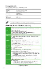
Страница 6: ...al characteristics of individual CPUs Please refer to Memory QVL for details DDR4 2666MHz and higher memory modules will run at max 2666MHz on Intel 8th Gen 6 core or higher processors Refer to www asus com for the Memory QVL Qualified Vendors List Expansion slots 1 x PCI Express 3 0 2 0 x16 slot 2 x PCI Express 3 0 2 0 x1 slots 1 x PCI slot Graphics Integrated graphics processor Intel HD Graphics...

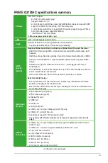
Страница 7: ...board 24 7 Reliability Tested under temperature up to 45 C and humidity up to 80 to ensure handle diverse environment Overcurrent Protection Short circuit prevention protects your system Easy Assembly Design Fixed position Color coded Connectors Enable easy identification and cable matching speeding up the production line Box Headers USB headers are box style enabling fast connector installation a...

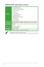
Страница 8: ... x Chassis Intrusion header 1 x Clear CMOS header 1 x MONO out header with Amp IC 1 x DIS ME jumper 1 x LPC debug header TPM 2 0 IC Onboard BIOS features 192Mb Flash ROM UEFI AMI BIOS PnP SM BIOS 3 1 ACPI 6 1 Multi language BIOS ASUS Self Recovering BIOS ASUS Event log ASUS Commercial Kit Manageability WOL PXE Support DVD Drivers ASUS Commercial BIOS Kits ASUS Watchdog timer OS support Windows 10 ...

Страница 9: ...mage to motherboard components Place this side towards the rear of the chassis Scan the QR code to get the detailed pin definitions PCI PCIEX1_1 PCIEX1_2 SPEAKER CHASSIS DIS_ME CLRTC F_PANEL LPC_DEBUG LPT U31G1_56 U31G1_78 AAFP MONO_OUT EATX12V EATXPWR CHA_FAN2 CPU_FAN CHA_FAN1 BATTERY PCIEX16 Super I O ASM 1083 ALC 887 DIGI VRM 24 4cm 9 6in 24 4cm 9 6in LGA1151 Intel Q370 Intel I219LM DDR4 DIMM_B...

Страница 10: ...T forget to connect the 8 pin EATX 12V power plug Otherwise the system will not boot up We recommend that you use a PSU with higher power output when configuring a system with more power consuming devices or when you intend to install additional devices The system may become unstable or may not boot up if the power is inadequate If you are uncertain about the minimum power supply requirement for y...

Страница 11: ...nect one end of the chassis intrusion sensor or switch cable to this connector The chassis intrusion sensor or switch sends a high level signal to this connector when a chassis component is removed or replaced The signal is then generated as a chassis intrusion event By default the pin labeled Chassis Signal and Ground are shorted with a jumper cap Remove the jumper caps only when you intend to us...

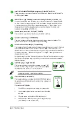
Страница 12: ...ices such as a printer LPT standardizes as IEEE 1284 which is the parallel port interface on IBM PC compatible computers Serial port connectors 10 1 pin COM Connect the serial port module cable to any of these connectors then install the module to a slot opening at the back of the system chassis Front panel audio connector 10 1 pin AAFP This connector is for a chassis mounted front panel audio I O...

Страница 13: ...the subsystem is capable of driving a speaker load of 2 Ohms at 2 Watts rms PCI Express 3 0 2 0 x1 slots This motherboard has two PCI Express 3 0 2 0 x1 slots that support PCI Express x1 network cards SCSI cards and other cards that comply with the PCI Express specifications PCI Express 3 0 2 0 x16 slot This motherboard supports a PCI Express 3 0 2 0 x16 graphic card that complies with the PCI Exp...

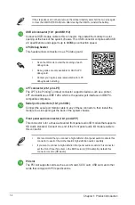
Страница 14: ... 2 ports are controlled by the xHCI controller We strongly recommend that you connect USB 3 1 Gen 2 devices to USB 3 1 Gen 2 ports for faster and better performance from your USB 3 1 Gen 2 devices Rear panel connectors 1 2 3 4 5 7 8 10 11 6 9 LAN port Speed LED Activity Link LED Activity Link LED Speed LED Status Description Status Description Off No link OFF 10Mbps connection Orange Linked ORANGE...

Страница 15: ...e ports are for a DisplayPort compatible device 10 HDMI port This port is for a High Definition Multimedia Interface HDMI connector and is HDCP compliant allowing playback of HD DVD Blu ray and other protected content 11 PS 2 Keyboard port purple This port is for a PS 2 keyboard Audio 2 1 4 1 5 1 or 7 1 channel configuration Port Headset 2 1 channel 4 1 channel 5 1 channel 7 1 channel Light Blue R...

Страница 16: ... the socket and the socket contacts are not bent Contact your retailer immediately if the PnP cap is missing or if you see any damage to the PnP cap socket contacts motherboard components Keep the cap after installing the motherboard ASUS will process Return Merchandise Authorization RMA requests only if the motherboard comes with the cap on the LGA1151 socket The product warranty does not cover d...

Страница 17: ... get the correct memory modules DDR4 2666MHz and higher memory modules will run at max 2666MHz on Intel 8th Gen 6 core or higher processors Memory modules with memory frequency higher than 2133 MHz and its corresponding timing or the loaded X M P Profile is not the JEDEC memory standard The stability and compatibility of these memory modules depend on the CPU s capabilities and other installed dev...

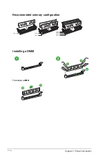
Страница 18: ...1 10 Chapter 1 Product introduction Installing a DIMM 1 2 To remove a DIMM B A B A A Recommended memory configuration DIMM_A1 DIMM_A2 DIMM_B2 DIMM_B1 DIMM_B2 DIMM_A2 DIMM_B2 ...

Страница 19: ...parameters The BIOS screens include navigation keys and brief online help to guide you in using the BIOS Setup program Entering BIOS Setup at startup To enter BIOS Setup at startup Press Delete or F2 during the Power On Self Test POST If you do not press Delete or F2 POST continues with its routines Entering BIOS Setup after POST To enter BIOS Setup after POST Press Ctrl Alt Del simultaneously Pre...

Страница 20: ...01 09 2017 System Time 21 25 25 Access Level Administrator Security BIOS Information Menu bar Menu items General Help Configuration fields Sub menu item The BIOS setup screens shown in this section are for reference purposes only and may not exactly match what you see on your screen Visit the ASUS website at www asus com to download the latest BIOS file for this motherboard If the system becomes u...

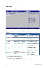
Страница 21: ... Current occurred CPU Over Heating Error CPU Over Voltage Error A built in event log enables easier troubleshooting by capturing useful system information including Event Log You can access Event Log from the Tool menu Select Screen Select Item Enter Select Change Opt F1 General Help F2 Previous Values F5 Optimized Defaults F10 Save Exit ESC Exit Version 2 19 1269 Copyright C 2017 American Megatre...

Страница 22: ...his option or if you press Esc a confirmation window appears Select OK to discard changes and exit Launch EFI Shell from USB drives This option allows you to attempt to launch the EFI Shell application shellx64 efi from one of the available USB devices Exit menu The Exit menu items allow you to load the optimal default values for the BIOS items and save or discard your changes to the BIOS items Se...

Страница 23: ...cause harmful interference to radio communications However there is no guarantee that interference will not occur in a particular installation If this equipment does cause harmful interference to radio or television reception which can be determined by turning the equipment off and on the user is encouraged to try to correct the interference by one or more of the following measures Reorient or rel...

Страница 24: ...CAN ICES 3 B NMB 3 B Déclaration de conformité de Innovation Sciences et Développement économique Canada ISED Le présent appareil est conforme aux CNR d Innovation Sciences et Développement économique Canada applicables aux appareils radio exempts de licence L exploitation est autorisée aux deux conditions suivantes 1 l appareil ne doit pas produire de brouillage et 2 l utilisateur de l appareil d...

Страница 25: ...and takeback programs come from our commitment to the highest standards for protecting our environment We believe in providing solutions for you to be able to responsibly recycle our products batteries other components as well as the packaging materials Please go to http csr asus com english Takeback htm for detailed recycling information in different regions Regional notice for California WARNING...

Страница 26: ...ниям и другим соответствующим условиям соответствующих директив Подробную информацию пожалуйста смотрите на www asus com support Български С настоящото ASUSTeK Computer Inc декларира че това устройство е в съответствие със съществените изисквания и другите приложими постановления на свързаните директиви Пълният текст на декларацията за съответствие на ЕС е достъпна на адрес www asus com support Hr...

Страница 27: ...L America Address 800 Corporate Way Fremont CA 94539 USA Telephone 1 510 739 3777 Fax 1 510 608 4555 Web site http www asus com us Technical Support Support fax 1 812 284 0883 Telephone 1 812 282 2787 Online support http qr asus com techserv ASUS COMPUTER GmbH Germany and Austria Address Harkort Str 21 23 40880 Ratingen Germany Fax 49 2102 959931 Web site http www asus com de Online contact http e...

Страница 28: ...08 4555 hereby declares that the product Product Name Motherboard Model Number PRIME Q370M C compliance statement This device complies with part 15 of the FCC Rules Operation is subject to the following two conditions 1 This device may not cause harmful interference and 2 this device must accept any interference received including interference that may cause undesired operation Ver 180125 ...

Отзывы: