


Communication extension card
-54-
EtherCAT communication card
4.5
Overview
1.
Thanks for choosing ASTRAADA EC-TX508 communication cards. This manual describes the function
specifications, installation, basic operation and settings, and information about the EtherCAT protocol.
To ensure that you install and operate the product properly, read this manual and the communication
protocol section in the VFD operation manual carefully before you use the product.
2.
This manual only describes how to operate the EC-TX508 communication card and the related
commands but does not provide details about the EtherCAT protocol. For more information about the
EtherCAT protocol, read the related specialized articles or books.
3.
EC-TX508 communication card is defined as an EtherCAT slave station communication card and is used
on a VFD that supports EtherCAT communication.
4.
The EtherCAT communication of this communication card supports two types of process data for
reading data from and writing data to VFDs. They are PDOs (process data objects) and SDOs (service
data objects) for reading data from and writing data to the object dictionary defined by the
manufacturer.
4.6
Features
1.
Supported functions
➢
Supports the EtherCAT COE 402 protocol.
➢
Supports automatic network address setting
2.
Supported services
➢
Supports the PDO service
➢
Supports the SDO service
➢
Supports the object dictionary defined by the manufacturer
➢
Allowing SDOs to read data from and write data to VFD function codes
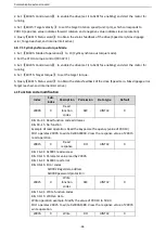
3.
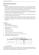
Supported EtherCAT synchronization cycle
Table 0-1
Supported synchronization cycle
Item
Supported specification
Synchronization cycle
250us
500us
1ms
2ms
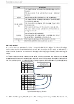
4.
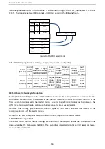
Communication ports
Standard RJ45 ports are used in EtherCAT communication. The communication card provides two RJ45 ports
with transmission direction defined. Figure 6-1 shows the ports. IN (indicating input) and OUT (indicating
ouput) are EtherCAT wiring network ports. Table 6-2 describes the port pins.


