DRV-28 inverter
s Installation guide
-26-
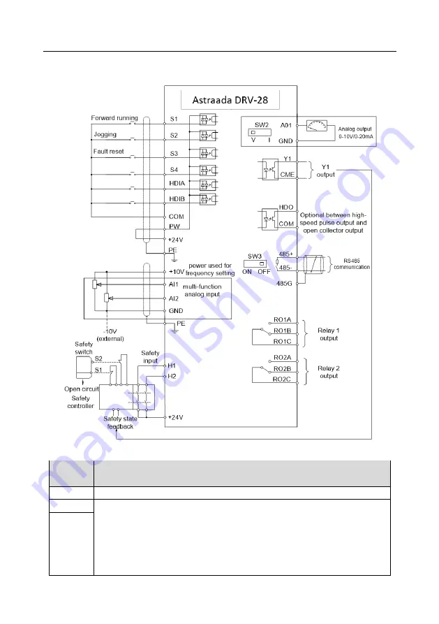
4.4 Standard wiring of control circuit
4.4.1 Wiring diagram of basic control circuit
Fig 4.15 Wiring diagram of control circuit
Terminal
name
Instruction
+10V
The inverter pr10.5V power
AI1
1.
Input range: AI1 voltage/current can choose 0
–10/ 0–20mA;
AI2: -10V
–+10V voltage;
2.
Input impedance: 20kΩ during voltage input; 250Ω during current input;
3.
AI1 voltage or current input is set by P05.50;
4.
Resolution ratio: When 10V corresponds to 50Hz, the min. resolution ratio is
5mV;
AI2


