DRV-28 inverter
s Extension cards
-308-
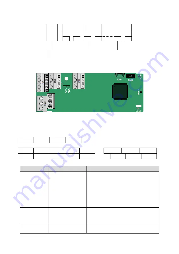
Master
device
Slave device 2
RJ45
RJ45
Slave device 1
RJ45
RJ45
Slave device n
RJ45
RJ45
Switch
A.7 Programmable extension card function description
A.7.1 Programmable extension card
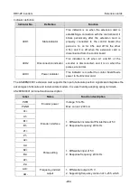
–– AS28PLC0001
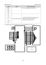
The terminals are arranged as follows:
SW1 is the start/stop switch of the programmable extension card. CN6 is the program download port,
and you can connect to a computer by using a standard USB cable. COM and CME are shorted
through J1 before delivery.
PY1
PY2
CME
COM
COM
PS1
PS2
PS3
PRO1A
PRO1B
PRO1C
PW
+24V
PS4
PS5
PS6
PRO2A
PRO2C
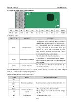
Indicator definition
Indicator No.
Definition
Function
LED3
State indicator
This indicator is on when the extension card is
establishing a connection with the control board;
it blinks periodically after the extension card is
properly connected to the control board (the
period is 1s, on for 0.5s, and off for the other
0.5s); and it is off when the extension card is
disconnected from the control board.
LED4
PLC running state
indicator
This indicator is on when the DIP switch is
turned to RUN (run the PLC); and it is off when
the switch is turned to STOP (stop the PLC).
LED5
Power indicator
This indicator is on after the control board feeds
power to the communication card.


