DRV-28 inverter
s Extension cards
-289-
Category
Label
Name
Function description
3. Deviation ±0.5%; input of 5 V or 10 mA or
higher at the temperature of 25°C
Digital
input/output
S5—COM
Digital input 1
1. Internal impedance: 3.3 kΩ
2. Power input range: 12–30 V
3. Bidirectional input terminal
4. Max. input frequency: 1 kHz
S6—COM
Digital input 2
S7—COM
Digital input 3
S8—COM
Digital input 4
Y2—CME
Digital output
1. Switch capacity: 200 mA/30 V
2. Output frequency range: 0–1 kHz
3. The terminals CME and COM are
shorted through J3 before delivery.
Relay
output
R03A
NO contact of
relay 3
1. Contact capacity: 3A/AC 250 V, 1 A/DC
30 V
2. Do not use them as high-frequency
digital outputs.
R03B
NC contact of
relay 3
R03C
Common contact
of relay 3
R04A
NO contact of
relay 4
R04C
Common contact
of relay 4
A.5
Encoder extension card function description
A.5.1 Multi-function incremental
encoder card ––
AS28ENC0003
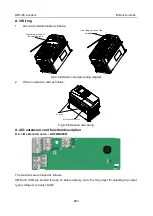
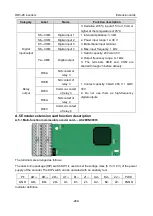
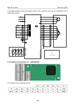
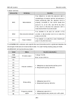
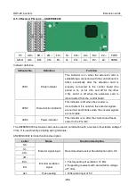
The terminals are arranged as follows:
The dual in-line package (DIP) switch SW1 is used to set the voltage class (5 V or 12 V) of the power
supply of the encoder. The DIP switch can be operated with an auxiliary tool.
PE
AO+
BO+
ZO+
A1+
B1+
Z1+
A2+
B2+
Z2+
PWR
GND
AO-
BO-
ZO-
A1-
B1-
Z1-
A2-
B2-
Z2-
PGND
Indicator definition

