background image

Aston Technologies Inc.


www.astontechusa.com


-  12  - 

succeeds. 

    5.1.3 Self-calibration trouble shooting 

Troubles 

Reasons 

Solutions 

Display Err, -8- 

1.  Do  not  place  100g 
lead block. 
2. Lead wire of pressure 
sensor breaks. 
3.  Main  board  goes 
wrong. 

1. Place 100g lead block. 
2. Check and connect. 
3. Replace main board. 

Error  is  much  greater 
after self-calibrating. 

1.  May  be  error  of  tire 
itself is much greater. 
2. 

Three 

memory 

parameters confuse. 

1.  Replace  a  balanced 
standard tire. 
2.  Adjust  three  memory 
parameters 

and 

self-calibrate. 

The  value  100g  that  is 
displayed  is  inaccurate, 
the  position  of  lead 
block is not beneath the 
main  shaft,  and  the  tire 
can  be  balanced  with 
many lead blocks. 

1.  The  tire  is  not 
standard  or  there  are 
sundries in the tire 
2.  Memory  values  dis 
and  SFA  do  not  adjust 
well. 
3.  The  value  that  is 
display is inaccurate. 

1.  Replace  a  standard 
tire. 
2.1 If the displayed value 
is high, reduce the value 
dis. 
2.2  If  the  displayed 
value is low, increase the 
value dis. 
2.3  When  lead  block  is 
away  from  the  operator, 
increase the value SFA. 
2.4  When  lead  block  is 
back  from  the  operator, 
reduce the value SFA. 
3.  Shoot  according  to 
trouble shooting. 

If do not resolve by the above methods, please contact the manufacturer. 

Caution: 

After  replacing  main  board,  power  panel,  phase  position  and 

pressure  position,  self-calibration  must  be  carried  out  over  again.  When 
replace main board, setup its parameters according to original parameters, the 
method sees 5.2. And self-calibrate over again after modifying. 

  5.2 Correcting memory data 

    Because  incorrect  operations  and  other  reasons  result  in  losing  memory 
parameters,  adjust  as  follows  and  make  the  computer  return  normal  work. 
Correct parameter setup can guarantee its balancing precision. 

  Trouble:

 After self-calibrating, the phase position is inaccurate or the error 

is too greater. 

Correcting method as follows: 

1.  First  press  the  keys  R  &  START,  the 

Содержание ADP-2000A

Страница 1: ...Aston Technologies Inc www astontechusa com 1 Wheel Balancer User s Manual Model ADP 2000A...

Страница 2: ...4 WHEEL BALANCING OPERATION PROCESS 6 4 1 ELECTRICAL CONNECTION 6 4 2 WHEEL MOUNTING 6 4 2 1 Tire mounting 7 4 2 2 Tire mounting with special flange 7 4 3 DIMENSION INPUT 7 4 4 BALANCING MODES 8 4 5 B...

Страница 3: ...s imported computer parts it has world advanced electric drive system and its life can be up to ten years High strength protective cover optional it accords with national safety operating procedure Un...

Страница 4: ...ce using alcohol or gasoline tighten the screw mandrel tightly on the main shaft with spanner 2 3 Warning Ii is recommended that regulated power supply is adopted in the unstable power zone Please rea...

Страница 5: ...airiness area 3 CONTROL PANEL GRAPHICS Display unbalancing value inside the wheel edge Display unbalancing value outside the wheel edge Display unbalancing position inside the wheel edge Display unbal...

Страница 6: ...tion Only press the keys with hands and do not press the keys using clamp and any other sharp things 4 WHEEL BALANCING OPERATION PROCESS 4 1 Electrical connection Open the power switch and then displa...

Страница 7: ...washer nut 4 2 2 Tire mounting with special flange Install the flange on the adapter tighten it with bolt Fix the screw mandrel on the main shaft Select the proper cone to fit over on the main shaft T...

Страница 8: ...nput dimension L B Measure the width value L B of rim with width calipers Press the value increases Press the value reduces Until display the value L B that is measured Then input dimension D Find the...

Страница 9: ...U1 Balance alloy rim by placing the adhesive weights onto the rim shoulders The adhesive position of wheel weights as shown in left Figure ALU2 Balance alloy rim by placing the adhesive weights that a...

Страница 10: ...e by hand to extend the motor life 2 Check whether input dimension is wrong press the key R to automatically defect the value A L D 3 Check whether balancing modes accord with the tire structure See d...

Страница 11: ...that self calibration ends 4 Press the key START again if displaying 00 100 4g and outer indicator LEDs blink 100g balancing weight should be beneath the main shaft allow having 4 error which indicat...

Страница 12: ...ard tire 2 1 If the displayed value is high reduce the value dis 2 2 If the displayed value is low increase the value dis 2 3 When lead block is away from the operator increase the value SFA 2 4 When...

Страница 13: ...static balancing parameters When offset data are too many adjust to shown in Fig 3 Fig 3 Standard Memory Correcting value 100g of inner of static balancing 4 Then press the key as Fig 4 shown if the...

Страница 14: ...Err3 Unbalance amount of wheel is much greater Replace wheel or self calibrate over again Display Err4 1 If reversal phase position is connected incorrectly 2 If corotation the position of sensor goe...

Страница 15: ...place mainboard 3 Self calibrate over again Display value but not brake 1 Brake system is damaged 2 External disturbs 1 Replace power panel 2 Start over again Twice dismounting error is more than 10g...

Страница 16: ...chusa com 16 Steps 1 Loosen nuts 2 Drying sensors 3 First tighten nut and then tighten nut 4 First tighten nut and then tighten nut Caution The screw mandrel cannot touch the whole edge in the board 7...

Страница 17: ...com 17 TD01 Lock washer bolt 1 TD02 Calipers 1 TD03 Balancing pliers 1 TD04 Screw mandrel 1 TD05 Flange 1 1 TD06 Flange 2 1 TD07 Cone 1 1 TD08 Cone 2 1 TD09 Cone 3 1 TD10 Cone 4 1 TD11 Cone 5 1 Acces...

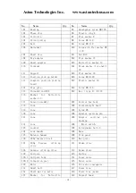
Страница 18: ...pole B18 Screw M6 16 115 Threaded rod M12 B19 Key type A 4 18 116 Washer for Belleville washer 12 117 Sensor assembly 201 Control box body 118 Cone 202 Counterweight head 119 Cone 203 Screw M5 120 Con...

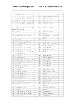
Страница 19: ...uick insert joint B27 Quick wrest straight terminal joint B52 muffler B28 Y circle B53 Screw M4 30 B29 Screw M8 20 B54 Elastic washer 6 B30 Block ring for shaft 16 B55 Flat washer 6 B31 Hexangular bol...

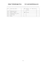
Страница 20: ...ton Technologies Inc www astontechusa com 20 321 Power main board 363 Washer for Belleville washer 322 Aluminium spacer 323 Plastic support B60 Screw 324 Aluminium alloy plate 325 Transformer 326 Rela...

Страница 21: ...Aston Technologies Inc www astontechusa com 21...

Страница 22: ...Aston Technologies Inc www astontechusa com 22...

Страница 23: ...Aston Technologies Inc www astontechusa com 23...

Страница 24: ...Aston Technologies Inc www astontechusa com 24...

Отзывы:

Похожие инструкции для ADP-2000A