background image


ASSA ABLOY, the global leader in


door opening solutions


© Copyright, 2011, all rights reserved 


PN# 500-22700


Rev. F, 03/11 


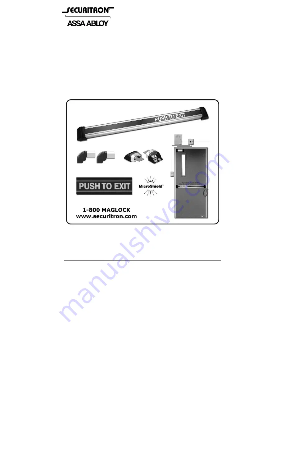
SERIES DSB DUAL SENSE BAR 

INSTALLATION and OPERATION 

INSTRUCTIONS 


Securitron Magnalock Corp. 

www.securitron.com 

 Tel 

800.624.5625 

[email protected] 


Содержание Securitron DSB Series

Страница 1: ...or opening solutions Copyright 2011 all rights reserved PN 500 22700 Rev F 03 11 SERIES DSB DUAL SENSE BAR INSTALLATION and OPERATION INSTRUCTIONS Securitron Magnalock Corp www securitron com Tel 800 624 5625 techsupport securitron com ...

Страница 2: ...nting platform for the bar and house the electronic PC boards and mechanical switching mechanisms within the bar 2 SPECIFICATIONS MECHANICAL ELECTRICAL Physical Size Height 3 76mm Depth 3 76mm from mounting surface Overall Length 36 Door 34 3 16 868mm 42 Door 40 3 16 1021mm 48 Door 46 3 16 1173mm Operating Force Maximum 15 Lbs 66 7N Environmental Recommended Temperature Range 32ºF 0ºC to 120ºF 49º...

Страница 3: ...DSB SHOULD ALWAYS BE VERIFIED AND APPROVED THROUGH LOCAL BUILDING CODE AND OR FIRE PREVENTION DEPARTMENTS 6 1 BAR POSITIONING AND MOUNTING HOLE MARKING Using a 1 Phillips screwdriver remove the screws and the end caps from both ends of the bar Verify that the bar is the correct length for the door If it appears that the bar is longer than it should be for the door see Section 6 6 for cutting instr...

Страница 4: ...ht between the door frame stops By using the assembled bar as a template the correct separation between the mounting holes will automatically be maintained After marking the hole locations verify that the centers of the holes are at the required distance as shown in Figure 4 Figure 3 Figure 4 ...

Страница 5: ...n firm pressure toward the mounting surface while collapsing the nut d Once the blind nut is adequately collapsed remove the tool from the installed nut by backing the cap screw out of the blind nut e Install all blind nuts by using the collapsing tool and repeating the previous steps f After all blind nuts are installed hold the bar in place over the blind nuts and secure into place with the plas...

Страница 6: ...y hole be located in the hinge side of the door at the position shown see Figure 4 This hole allows either the traditional cable with connector or the ElectroLynx wiring harness connectors to be pulled into the door DSB Traditional Wiring Wire routing from a hollow door implementing the traditional wiring method may be achieved using a door cord The TSB C included with the standard DSB may be moun...

Страница 7: ... may be used for shortening the DSB To determine the cut to length you may use two measurements to fit the existing opening or to replace an existing Securitron TSB 3 using the same mount holes If the TSB 3 length was not altered from the factory your new DSB will fit into the same mounting holes and hardware 1 If the bar does not fit the existing holes measure the center to center spacing of the ...

Страница 8: ...op of itself and applying a wire tie or electrical tape to secure the loop o Reconnect to the PC boards base mounts The two LED wire harnesses of an illuminated bar are interchangeable and may be plugged into either of the 2 pin connectors on the main TS PC board p Reinstall the touch sense wire ring terminal to the boss in the bar extrusion q Insert both of the end base mounts with their PC board...

Страница 9: ... 5 Orange Normally Open 1 6 Green Normally Closed 2 6 Blue Normally Open 2 7 N A Not assigned 7 N A Not assigned 8 N A Not assigned 8 N A Not assigned The male connector of the cable or ElectroLynx wire harness is plugged into the 8 pin female connector on the main circuit board so that the cable routes directly back into the end mount of the DSB The DSB is operated by a control relay which change...

Страница 10: ...ions and for integration with the Request to Exit REX function of an access control installation The following wiring diagrams Figures 13 and 14 show typical connections of the dual sense bar power supply and a fail safe lock in use on single and double door exits with an access control unit Figure 13 Single Door with Access Control Figure 14 Double Door with Access Control Request to Exit Input L...

Страница 11: ...ed exiting Also for most entry controls the REX input must be used for exiting to avoid an alarm condition at the door If the REX input alone is used for exiting a safety reliability problem will exist If the entry device malfunctions exit will not be possible and people may be trapped It is recommended that double break wiring which is supported by the DSB be used because of its two pole relay Th...

Страница 12: ... that power may not be getting to the sensor Inspect the connector that plugs into the main PC board to ensure that it is fully engaged and check for loose wires Finally verify that the ring terminal that connects the sensor to the bar has not come loose If the red LED does illuminate when you touch the bar and the door does not release try to mechanically actuate the door If the door still does n...

Страница 13: ...ot enough clearance at the ends of the bar See Section 6 2 The end mounts are not installed tightly and they have slipped causing the bar to bind on the ends Make sure the end mounts are horizontal and the bar end caps are not bound by twisted mounting tighten the mounting screws securely IF YOUR PROBLEM PERSISTS CALL SECURITRON 1 800 MAG LOCK B INSTALLATION OF TSB C BETWEEN DSB END MOUNT AND DOOR...

Страница 14: ...euse 2 DRILL HOLE IN BASE RISER 1 Determine which side of the base riser to feed the flexible door cord shield into 2 Scribe and or center punch the base riser at location shown NOTE Prior to drilling any holes the riser should be secured in a vise or similar clamping device that will safely hold the part while it is being drilled 3 Using a drill with a 1 8 diameter bit create a pilot hole at the ...

Страница 15: ...rt the door cord insert into the end of the flexible door cord shield 4 Slide the flexible door cord shield door cord insert first over the power cord from the non connector end and up to the hole in the side of the base riser as shown 5 Insert the door cord shield through the holes drilled in the part and up to the wire feed thru channel in the base riser 6 Using needle nose pliers install the E ...

Страница 16: ...OOR 1 Plug the power cord connector into the receptacle on the PC board 2 Insert the end mount assembly with the PC board attached back into the end of the bar 3 Reinstall the shipping clip if necessary to hold the bar together throughout the remaining installation process 4 Install the DSB to the door as prescribed in the DSB installation and operation instruction manual After the bar has been in...

Страница 17: ...PN 500 22700 Page 16 Rev F 03 11 10 MAGNACARE LIFETIME REPLACEMENT WARRANTY For warranty information visit www securitron com en site securitron About MagnaCare Warranty ...

Отзывы: