background image

1

11

11

ASRock  

960GM/U3S3 FX

  Motherboard

EnglishEnglishEnglishEnglishEnglish

Copyright Notice:

Copyright Notice:

Copyright Notice:

Copyright Notice:

Copyright Notice:

No part of this installation guide may be reproduced, transcribed, transmitted, or trans-

lated in any language, in any form or by any means, except duplication of documen-

tation by the purchaser for backup purpose, without written consent of ASRock Inc.

Products and corporate names appearing in this guide may or may not be registered

trademarks or copyrights of their respective companies, and are used only for identifica-

tion or explanation and to the owners’ benefit, without intent to infringe.

Disclaimer:

Disclaimer:

Disclaimer:

Disclaimer:

Disclaimer:

Specifications and information contained in this guide are furnished for informational

use only and subject to change without notice, and should not be constructed as a

commitment by ASRock. ASRock assumes no responsibility for any errors or omissions

that may appear in this guide.

With respect to the contents of this guide, ASRock does not provide warranty of any kind,

either expressed or implied, including but not limited to the implied warranties or

conditions of merchantability or fitness for a particular purpose. In no event shall

ASRock, its directors, officers, employees, or agents be liable for any indirect, special,

incidental, or consequential damages  (including damages for loss of profits, loss of

business, loss of data, interruption of business and the like), even if ASRock has been

advised of the possibility of such damages arising from any defect or error in the guide

or product.

This device complies with Part 15 of the FCC Rules. Operation is subject to the

following two conditions:

(1) this device may not cause harmful interference, and

(2) this device must accept any interference received, including interference that

may cause undesired operation.

Published December 2011

Copyright

©

2011 ASRock INC. All rights reserved.

CALIFORNIA, USA ONLY

The Lithium battery adopted on this motherboard contains Perchlorate, a toxic

substance controlled in Perchlorate Best Management Practices (BMP) regulations

passed by the California Legislature. When you discard the Lithium battery in

California, USA, please follow the related regulations in advance.

“Perchlorate Material-special handling may apply, see

www.dtsc.ca.gov/hazardouswaste/perchlorate”

ASRock Website: http://www.asrock.com

Содержание U3S3 FX

Страница 1: ...pressed or implied including but not limited to the implied warranties or conditions of merchantability or fitness for a particular purpose In no event shall ASRock its directors officers employees or agents be liable for any indirect special incidental or consequential damages including damages for loss of profits loss of business loss of data interruption of business and the like even if ASRock ...

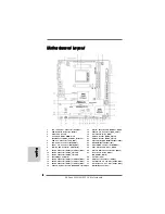
Страница 2: ...Module Header CIR1 6 ATX Power Connector ATXPWR1 23 Infrared Module Header IR1 7 Power Fan Connector PWR_FAN1 24 Clear CMOS Jumper CLRCMOS1 8 Primary IDE Connector IDE1 Blue 25 Print Port Header LPT1 White 9 SATA2 Connector SATAII_4 PORT 3 Blue 26 Internal Audio Connector CD1 Black 10 SATA3 Connector SATA3_2 White 27 Front Panel Audio Header 11 SATA3 Connector SATA3_1 White HD_AUDIO1 White 12 Sout...

Страница 3: ... and click ok Choose 2CH or 4CH and then you are allowed to select Realtek HDA Primary output to use Rear Speaker and Front Speaker or select Realtek HDA Audio 2nd output to use front panel audio Then reboot your system For Windows 7 VistaTM After restarting your computer please double click Realtek HD Audio Manager on the system tray Set Speaker Configuration to Quadraphonic or Stereo Click Devic...

Страница 4: ...ons and the BIOS software might be updated the content of this manual will be subject to change without notice In case any modifications of this manual occur the updated version will be available on ASRock website without further notice You may find the latest VGA cards and CPU support lists on ASRock website as well ASRock website http www asrock com If you require technical support related to th...

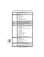
Страница 5: ...bridge AMD 760G Southbridge AMD SB710 Memory Dual Channel DDR3 Memory Technology see CAUTION 2 2 x DDR3 DIMM slots SupportDDR3 1866 OC 1600 OC 1333 1066 800 non ECC un buffered memory see CAUTION 3 Max capacity of system memory 16GB see CAUTION 4 Expansion Slot 1 x PCI Express 2 0 x16 slot blue x16 mode 1 x PCI Express 2 0 x1 slot 1 x PCI slot Graphics Integrated AMD Radeon HD 3000 graphics DX10 c...

Страница 6: ...A2 3 0Gb s connectors support RAID RAID 0 RAID 1 RAID 10 and JBOD NCQ AHCI and Hot Plug functions see CAUTION 6 2 x SATA3 6 0 Gb s connectors 1 x ATA133 IDE connector supports 2 x IDE devices 1 x IR header 1 x CIR header 1 x Print port header 1 x COM port header CPU Chassis Power FAN connector 24 pin ATX power connector 4 pin 12V power connector CD in header Front panel audio connector 2 x USB 2 0...

Страница 7: ...nstant Boot ASRock Instant Flash see CAUTION 9 ASRock OC DNA see CAUTION 10 ASRock APP Charger see CAUTION 11 ASRock SmartView see CAUTION 12 ASRock XFast USB see CAUTION 13 ASRock XFast LAN see CAUTION 14 ASRock XFast RAM see CAUTION 15 Hybrid Booster CPU Frequency Stepless Control see CAUTION 16 ASRock U COP see CAUTION 17 Boot Failure Guard B F G Hardware CPU Temperature Sensing Monitor Chassis...

Страница 8: ...latest information 6 Before installing SATAII hard disk to SATAII connector please read the SATAII Hard Disk Setup Guide on page 27 of User Manual in the support CD to adjust your SATAII hard disk drive to SATAII mode You can also connect SATA hard disk to SATAII connector directly 7 It is a user friendly ASRock overclocking tool which allows you to surveil your system by hardware monitor function...

Страница 9: ... Please be noticed that the OC profile can only be shared and worked on the same motherboard 11 If you desire a faster less restricted way of charging your Apple devices such as iPhone iPod iPad Touch ASRock has prepared a wonderful solution for you ASRock APP Charger Simply installing the APP Charger driver it makes your iPhone charged much quickly from your computer and up to 40 faster than befo...

Страница 10: ...r lifespan 16 Although this motherboard offers stepless control it is not recom mended to perform over clocking Frequencies other than the recom mended CPU bus frequencies may cause the instability of the system or damage the CPU 17 While CPU overheat is detected the system will automatically shutdown Before you resume the system please check if the CPU fan on the motherboard functions properly an...

Страница 11: ...is switched off or the power cord is detached from the power supply Failure to do so may cause severe damage to the motherboard peripherals and or components 1 Unplug the power cord from the wall socket before touching any component 2 To avoid damaging the motherboard components due to static electricity NEVER place your motherboard directly on the carpet or the like Also remember to use a grounde...

Страница 12: ... indicate that it is locked 2 2 2 2 2 2 2 2 2 2 Installation of CPU Fan and Heatsink Installation of CPU Fan and Heatsink Installation of CPU Fan and Heatsink Installation of CPU Fan and Heatsink Installation of CPU Fan and Heatsink After you install the CPU into this motherboard it is necessary to install a larger heatsink and cooling fan to dissipate heat You also need to spray thermal grease be...

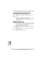
Страница 13: ...3 slot otherwise this motherboard and DIMM may be damaged 2 If you install only one memory module or two non identical memory modules it is unable to activate the Dual Channel Memory Technology Installing a DIMM Installing a DIMM Installing a DIMM Installing a DIMM Installing a DIMM Please make sure to disconnect power supply before adding or removing DIMMs or the system components Step 1 Unlock a...

Страница 14: ...it LAN card SATA2 card etc PCIE2 PCIE x16 slot Blue is used for PCI Express cards with x16 lane width graphics cards Installing an expansion card Installing an expansion card Installing an expansion card Installing an expansion card Installing an expansion card Step 1 Before installing the expansion card please make sure that the power supply is switched off or the power cord is unplugged Please r...

Страница 15: ...of dual monitor feature without installing any add on VGA card to this motherboard This motherboard also provides independent display controllers for DVI D and D Sub to support dual VGA output so that DVI D and D sub can drive same or different display contents To enable dual monitor feature please follow the below steps 1 Connect the DVI D monitor cable to the DVI D port on the I O panel And conn...

Страница 16: ...ish to be your primary monitor and then select Primary When you use multiple monitors with your card one monitor will always be Primary and all additional monitors will be designated as Secondary C Select the display icon identified by the number 2 D Click Extend my Windows desktop onto this monitor E Right click the display icon and select Attached if necessary F Set the Screen Resolution and Col...

Страница 17: ...l entertainment content that uses the DVI interface HDCP is a copy protection scheme to eliminate the possibility of intercepting digital data midstream between the video source or transmitter such as a computer DVD player or set top box and the digital display or receiver such as a monitor television or projector In other words HDCP specification is designed to protect the integrity of content as...

Страница 18: ...ront USB port If Multi Angle CIR Receiver cannot successfully receive the infrared signals from MCE Remote Controller please try to install it to the other front USB port 1 2 4 3 5 USB 2 0 header 9 pin blue CIR header 4 pin white 3 CIR sensors in different angles 1 Only one of the front USB port can support CIR function When the CIR function is enabled the other port will remain USB function 2 Mul...

Страница 19: ...S1 see p 2 No 24 Note CLRCMOS1 allows you to clear the data in CMOS The data in CMOS includes system setup information such as system password date time and system setup parameters To clear and reset the system parameters to default setup please turn off the computer and unplug the power cord from the power supply After waiting for 15 seconds use a jumper cap to short pin2 and pin3 on CLRCMOS1 for...

Страница 20: ...TAII SATAII_1 PORT 0 connectors support SATAII see p 2 No 15 or SATA hard disk for internal SATAII_2 PORT 1 storage devices The current see p 2 No 14 SATAII interface allows up to SATAII_3 PORT 2 3 0 Gb s data transfer rate see p 2 No 13 SATAII_4 PORT 3 see p 2 No 9 connect the black end to the IDE devices connect the blue end to the motherboard 80 conductor ATA 66 100 133 cable Serial ATA SATA Ei...

Страница 21: ...n support two USB 2 0 ports 9 pin USB8_9 see p 2 No 20 Print Port Header This is an interface for print 25 pin LPT1 port cable that allows see p 2 No 25 convenient connection of printer devices Consumer Infrared Module Header This header can be used to 4 pin CIR1 connect the remote see p 2 No 22 controller receiver Infrared Module Header This header supports an 5 pin IR1 optional wireless transmit...

Страница 22: ... the front mic For Windows XP XP 64 bit OS Select Mixer Select Recorder Then click FrontMic For Windows 7 7 64 bit VistaTM VistaTM 64 bit OS Go to the FrontMic Tab in the Realtek Control panel Adjust Recording Volume System Panel Header This header accommodates 9 pin PANEL1 several system front panel see p 2 No 17 functions Chassis Speaker Header Please connect the chassis 4 pin SPEAKER 1 speaker ...

Страница 23: ... 3 Connected 20 Pin ATX Power Supply Installation Though this motherboard provides 24 pin ATX power connector it can still work if you adopt a traditional 20 pin ATX power supply To use the 20 pin ATX power supply please plug your power supply along with Pin 1 and Pin 13 ATX Power Connector Please connect an ATX power 24 pin ATXPWR1 supply to this connector see p 2 No 6 12 1 24 13 12 1 24 13 ATX 1...

Страница 24: ...e Using SATA SATA2 SATA3 HDDs without NCQ and Hot Plug functions IDE mode STEP 1 Set up BIOS A Enter BIOS SETUP UTILITY Advanced screen Storage Configuration B Set the SATAOperation Mode option to IDE for SATAII_1 to SATAII_4 ports Set the Onboard SATA3 Operation Mode option to IDE for SATA3_1 and SATA3_2 ports STEP 2 Install Windows XP XP 64 bit OS on your system 2 11 2 11 2 11 2 11 2 11 Installi...

Страница 25: ...TA SATA2 SATA3 HDDs without NCQ and Hot Plug functions IDE mode Using SATA SATA2 SATA3 HDDs with NCQ and Hot Plug functions AHCI mode STEP 1 Set Up BIOS A Enter BIOS SETUP UTILITY Advanced screen Storage Configuration B Set the SATA Operation Mode option to AHCI for SATAII_1 to SATAII_4 ports Set the Onboard SATA3 Operation Mode option to AHCI for SATA3_1 and SATA3_2 ports STEP 2 Install Windows 7...

Страница 26: ...For the detailed information about BIOS Setup please refer to the User Manual PDF file contained in the Support CD 4 Sof 4 Sof 4 Sof 4 Sof 4 Software Suppor tware Suppor tware Suppor tware Suppor tware Support CD information t CD information t CD information t CD information t CD information This motherboard supports various Microsoft Windows operating systems 7 7 64 bit VistaTM VistaTM 64 bit XP ...

Страница 27: ... sich Motherboard Spezifikationen und BIOS Software verändern können kann der Inhalt dieses Handbuches ebenfalls jederzeit geändert werden Für den Fall dass sich Änderungen an diesem Handbuch ergeben wird eine neue Version auf der ASRock Website ohne weitere Ankündigung verfügbar sein Die neuesten Grafikkarten und unterstützten CPUs sind auch auf der ASRock Website aufgelistet ASRock Website http ...

Страница 28: ...T 1 Unterstützt Hyper Transport 3 0 Technologie HT 3 0 Chipsatz Northbridge AMD 760G Southbridge AMD 710 Speicher Unterstützung von Dual Kanal Speichertechnologie siehe VORSICHT 2 2 x Steckplätze für DDR3 UnterstütztDDR3 1866 OC 1600 OC 1333 1066 800 non ECC ungepufferter Speicher siehe VORSICHT 3 Max Kapazität des Systemspeichers 16GB siehe VORSICHT 4 Erweiterungs 1 x PCI Express 2 0 x16 Steckpla...

Страница 29: ...udioeingang Lautsprecher vorne Mikrofon SATA3 2 x ASMedia ASM1061 SATA 3 Anschlüsse 6 0 Gb s unterstützt NCQ AHCI und Hot Plug Hot Plugging Funktionen USB 3 0 2 x USB 3 0 Ports durch Etron EJ168A unterstützt USB 1 0 2 0 3 0 mit bis zu 5 Gb s Anschlüsse 4 x SATA2 Anschlüsse unterstützt bis 3 0 Gb s Datenübertragungsrate unterstützt RAID RAID 0 RAID 1 RAID 10 und JBOD NCQ AHCI und Hot Plug Funktione...

Страница 30: ...SRock SmartView siehe VORSICHT 12 ASRock XFast USB siehe VORSICHT 13 ASRock XFast LAN siehe VORSICHT 14 ASRock XFast RAM siehe VORSICHT 15 Hybrid Booster Schrittloser CPU Frequenz Kontrolle siehe VORSICHT 16 ASRock U COP siehe VORSICHT 17 Boot Failure Guard B F G Systemstartfehlerschutz Hardware Monitor CPU Temperatursensor Motherboardtemperaturerkennung Drehzahlmessung für CPU Gehäuse Stromlüfter...

Страница 31: ...SRock Internetseite http www asrock com 4 Durch Betriebssystem Einschränkungen kann die tatsächliche Speichergröße weniger als 4 GB betragen da unter Windows 7 Vista XP etwas Speicher zur Nutzung durch das System reserviert wird Unter Windows OS mit 64 Bit CPU besteht diese Einschränkung nicht 5 Die Maximalspeichergröße ist von den Chipshändler definiert und umgetauscht Bitte überprüfen Sie AMD we...

Страница 32: ...SRock exklusiv entwickeltes Dienstprogramm das Nutzern eine bequeme Möglichkeit bietet Übertaktungseinstellungen aufzuzeichnen und sie Anderen mitzuteilen Es hilft Ihnen Ihre Übertaktungsaufzeichnung im Betriebssystem zu speichern und vereinfacht den komplizierten Aufzeichnungsvorgang von Übertaktungseinstellungen Mit OC DNA können Sie Ihre Übertaktungseinstellungen als Profil abspeichern und Ihre...

Страница 33: ...nelleren Internetzugang mit den nachfolgenden Vorteilen LAN Anwendungspriorisierung Hiermit kon fi gurieren Sie auf ideale Weise Ihre Anwendungsprioritat und oder fugen neue Programme hinzu Niedrigere Latenzzeit bei Spielen Nach Einstel lung einer hoheren Online Gameprioritat kann hiermit die Latenzzeit bei Spielen herabgesetzt werden Datenverkehrsgestaltung Sie konnen Youtube Videos in HD anzeige...

Страница 34: ...ht wurde Bitte vergessen Sie nicht den Jumper wieder zu entfernen nachdem das CMOS gelöscht wurde Wenn Sie den CMOS Inhalt gleich nach dem Aktualisieren des BIOS löschen müssen müssen Sie zuerst das System starten und dann wieder ausschalten bevor Sie den CMOS Inhalt löschen oder mehr leisten können Gebrückt Offen CMOS löschen Default Einstellung Um die Wärmeableitung zu verbessern bitte nicht ver...

Страница 35: ...hlüsse setzen wird das Motherboard permanent beschädigt Anschluss Beschreibung Primärer IDE Anschluss blau 39 pin IDE1 siehe S 2 No 8 Blauer Anschluss Schwarzer Anschluss zum Motherboard zur Festplatte 80 adriges ATA 66 100 133 Kabel Hinweis Details entnehmen Sie bitte den Anweisungen Ihres IDE Gerätehändlers SATAII_1 PORT 0 SATAII_3 PORT 2 SATAII_2 PORT 1 SATAII_4 PORT 3 SATA3_1 SATA3_2 Seriell A...

Страница 36: ...uses ermöglicht siehe S 2 No 27 Ihnen eine bequeme Kontrolle über Audio Geräte Druckerport Anschlussleiste Dies ist eine Schnittstelle zum 25 pol LPT1 Anschluss eines Druckerport siehe S 2 No 25 Kabels mit dem Sie passende Drucker auf einfache Weise anschließen können Infrarot Modul Header Dieser Header unterstützt ein 5 pin IR1 optionales drahtloses Sende siehe S 2 No 23 und Empfangs Infrarotmodu...

Страница 37: ...an die AC 97 Audioleiste angeschlossen werden E So aktivieren Sie das Mikrofon an der Vorderseite Bei den Betriebssystemen Windows XP XP 64 Bit Wählen Sie Mixer Wählen Sie Recorder Rekorder Klicken Sie dann auf FrontMic Vorderes Mikrofon Bei den Betriebssystemen Windows 7 7 64 Bit VistaTM VistaTM 64 Bit Wählen Sie im Realtek Bedienfeld die FrontMic Vorderes Mikrofon Registerkarte Passen Sie die Re...

Страница 38: ...ATX 12 4 pin ATX12V1 Volt Stecker mit diesem siehe S 2 No 1 Anschluss verbinden müssen damit ausreichend Strom geliefert werden kann Andernfalls reicht der Strom nicht aus das System zu starten 12 1 24 13 CPU Lüfteranschluss Verbinden Sie das CPU 4 pin CPU_FAN1 Lüfterkabel mit diesem siehe S 2 No 5 Anschluss und passen Sie den schwarzen Draht dem Erdungsstift an 1 2 3 4 Obwohl dieses Motherboard e...

Страница 39: ...3 9 3 9 ASRock 960GM U3S3 FX Motherboard Deutsch Deutsch Deutsch Deutsch Deutsch COM Anschluss Header Dieser COM Anschluss 9 pin COM1 Header wird verwendet um siehe S 2 No 29 ein COM Anschlussmodul zu unterstützen ...

Страница 40: ...utzerhandbuch PDF Datei auf der Support CD 3 Software Support CD information 3 Software Support CD information 3 Software Support CD information 3 Software Support CD information 3 Software Support CD information Dieses Motherboard unterstützt eine Reiche von Microsoft Windows Betriebssystemen 7 7 64 Bit VistaTM VistaTM 64 Bit XP XP Media Center XP 64 Bit Die Ihrem Motherboard beigefügte Support C...

Страница 41: ... manuel est sujet à des changements sans notification Au cas où n importe qu elle modification intervenait sur ce manuel la version mise à jour serait disponible sur le site web ASRock sans nouvel avis Vous trouverez les listes de prise en charge des cartes VGA et CPU également sur le site Web ASRock Site web ASRock http www asrock com Si vous avez besoin de support technique en relation avec cett...

Страница 42: ...5 2 GT s Prend en charge la technologie Untied Overclocking voir ATTENTION 1 Prise en charge de la technologie Hyper Transport 3 0 HT 3 0 Chipsets Northbridge AMD 760G Southbridge AMD SB710 Mémoire Compatible avec la Technologie de Mémoire à Canal Double voir ATTENTION 2 2 x slots DIMM DDR3 SupporterDDR3 1866 OC 1600 OC 1333 1066 800 non ECC sans amortissement mémoire voir ATTENTION 3 Capacité max...

Страница 43: ...ortie ligne microphone SATA3 2 x connecteurs ASMedia ASM1061 SATA3 6 0 Gb s prennent en charge les fonctions NCQ AHCI et Hot Plug Branchement à chaud USB 3 0 2 x ports USB3 0 par Etron EJ168A prennent en charge USB 1 0 2 0 3 0 jusqu à 5 Gb s Connecteurs 4 x connecteurs SATA2 prennent en charge un taux de transfert de données pouvant aller jusqu à 3 0Go s supporte RAID RAID 0 RAID 1 RAID 10 et JBOD...

Страница 44: ... énergie intelligent voir ATTENTION 8 ASRock l Instant Boot ASRock Instant Flash voir ATTENTION 9 ASRock OC DNA voir ATTENTION 10 Chargeur ASRock APP voir ATTENTION 11 ASRock SmartView voir ATTENTION 12 ASRock XFast USB voir ATTENTION 13 ASRock XFast LAN voir ATTENTION 14 ASRock XFast RAM voir ATTENTION 15 L accélérateur hybride Contrôle direct de la fréquence CPU voir ATTENTION 16 ASRock U COP vo...

Страница 45: ...centes SVP 6 Avant d installer le disque dur SATAII au connecteur SATAII veuillez lire le Guide Installation du disque dur SATAII à la page 27 du Manuel de l utilisateur qui se trouve sur le CD de support pour régler votre lecteur de disque dur SATAII au mode SATAII Vous pouvez aussi directement connecter le disque dur SATA au connecteur SATAII 7 Il s agit d un usage facile ASRock overclocking out...

Страница 46: ...dar o novo ficheiro de BIOS numa unidade flash USB numa disquete ou num disco rígido em seguida poderá actualizar o BIOS com apenas alguns cliques sem ter de utilizar outra disquete ou outro complicado utilitário de flash Note que a unidade flash USB ou a unidade de disco rígido devem utilizar o sistema de ficheiros FAT32 16 12 10 Le nom même du logiciel OC DNA vous indique littéralement ce dont i...

Страница 47: ...e la latence dans les jeux Forme du trafi c Vous pouvez regarder des videos HD YouTube et te lecharger simultanement des fi chiers Analyse en temps reel de vos don nees Avec la fenetre d etat vous pouvez facilement reconnaitre les fl ux de donnees que vous etes en train de transferer 15 Il utilise à sa pleine capacité l espace mémoire que les processeurs du système d exploitation Windows OS 32 bit...

Страница 48: ...et débrancher le cordon d alimentation de l alimentation électrique Attendez 15 secondes puis utilisez un capuchon de cavalier pour court circuiter la broche 2 et la broche 3 sur CLRCMOS1 pendant 5 secondes Après avoir court circuité le cavalier Effacer la CMOS veuillez enlever le capuchon de cavalier Toutefois veuillez ne pas effacer la CMOS tout de suite après avoir mis le BIOS à jour Si vous av...

Страница 49: ...0 ATA SATAII prennent en charge voir p 2 fig 15 les disques durs SATA ou SATAII SATAII_2 PORT 1 pour les dispositifs de stockage voir p 2 fig 14 interne L interface SATAII SATAII_3 PORT 2 actuelle permet des taux voir p 2 fig 13 transferts de données pouvant SATAII_4 PORT 3 aller jusqu à 3 0 Go s voir p 2 fig 9 Fran Fran Fran Fran Français çais çais çais çais SATAII_1 PORT 0 SATAII_3 PORT 2 SATAII...

Страница 50: ...ommodes de périphériques audio Embase de port d impression AIl s agit d une interface pour le LPT1 25 broches câble du port d impression qui voir p 2 No 25 permet le raccordement pratique de périphériques d impression En tête du module infrarouge Cet en tête supporte un module IR1 br 5 infrarouge optionnel de voir p 2 No 23 transfert et de réception sans fil Barrette pour module à infrarouges gran...

Страница 51: ...charge la détection de fiche mais le fil de panneau sur le châssis doit prendre en charge le HDA pour fonctionner correctement Veuillez suivre les instructions dans notre manuel et le manuel de châssis afin installer votre système 2 Si vous utilisez le panneau audio AC 97 installez le sur l adaptateur audio du panneau avant conformément à la procédure ci dessous A Connectez Mic_IN MIC à MIC2_L B C...

Страница 52: ...er qu il est nécessaire 12VATX de connecter une unité ATX12V1 br 4 d alimentation électrique avec voir p 2 fig 1 prise ATX 12V sur ce connecteur afin d avoir une alimentation suffisante Faute de quoi il ne sera pas possible de mettre sous tension Bien que cette carte mère offre un support de Ventilateur silencieux ventilateur de CPU à 4 broches le ventilateur de CPU à 3 broches peut bien fonctionn...

Страница 53: ...nus et de choisir parmi les choix prédéterminés Pour des informations détaillées sur le BIOS veuillez consulter le Guide de l utilisateur fichier PDF dans le CD technique 3 Informations sur le CD de support 3 Informations sur le CD de support 3 Informations sur le CD de support 3 Informations sur le CD de support 3 Informations sur le CD de support Cette carte mère supporte divers systèmes d explo...

Страница 54: ...i pertanto il contenuto di questo manuale può subire variazioni senza preavviso Nel caso in cui questo manuale sia modificato la versione aggiornata sarà disponibile sul sito di ASRock senza altro avviso Sul sito ASRock si possono anche trovare le più recenti schede VGA e gli elenchi di CPU supportate ASRock website http www asrock com Se si necessita dell assistenza tecnica per questa scheda madr...

Страница 55: ... AMD SB710 Memoria Supporto tecnologia Dual Channel Memory vedi ATTENZIONE 2 2 x slot DDR3 DIMM SupportoDDR3 1866 OC 1600 OC 1333 1066 800 non ECC momoria senza buffer vedi ATTENZIONE 3 Capacità massima della memoria di sistema 16GB vedi ATTENZIONE 4 Slot di 1 x slot PCI Express 2 0 x16 blu a modalità x16 espansione 1 x slot PCI Express 2 0 x1 1 x slot PCI VGA su scheda Grafica AMD Radeon HD 3000 ...

Страница 56: ...Hot Plug USB 3 0 2 x Porte USB 3 0 Etron EJ168A supporto di USB 1 0 2 0 3 0 fino a 5Gb s Connettori 4 x connettori SATA2 3 0Go s sopporta RAID RAID 0 RAID 1 RAID 10 e JBOD NCQ AHCI e Collegamento a caldo vedi ATTENZIONE 6 2 x connettori SATA3 6 0Go s 1 x connettori ATA133 IDE supporta fino a 2 dispositivi IDE 1 x Collettore modulo infrarossi 1 x Connettore modulo infrarosso consumer 1 x Collettore...

Страница 57: ...SRock Risparmio intelligente dell energia vedi ATTENZIONE 8 ASRock Instant Boot ASRock Instant Flash vedi ATTENZIONE 9 ASRock OC DNA vedi ATTENZIONE 10 Caricatore ASRock APP Charger vedi ATTENZIONE 11 ASRock SmartView vedi ATTENZIONE 12 ASRock XFast USB vedi ATTENZIONE 13 ASRock XFast LAN vedi ATTENZIONE 14 ASRock XFast RAM vedi ATTENZIONE 15 Booster ibrido Stepless control per frequenza del proce...

Страница 58: ...ATAII leggere la Guida per la configurazione del disco rigido SATAII a pagina 27 del Manuale utente nel CD in dotazione in modo da poter predisporre il disco rigido SATAII per la modalità SATAII È anche possibile connettere il disco rigido SATA direttamente al connettore SATAII 7 Si tratta di uno strumento di sicronizzazione ASRock di face uso in grado di implementare il controllo del sistema tram...

Страница 59: ...iso e modificato solo sulla stessa scheda madre 11 Se vuoi un modo rapido e indipendente per caricare i dispositivi Apple come iPhone iPod iPad Touch ASRock ha preparato una soluzione meravigliosa ASRock APP Charger Basta installare il driver APP Charger per caricare l iPhone più rapidamente rispetto al computer con una velocità maggiore del 40 ASRock APP Charger permette di caricare simultaneamen...

Страница 60: ... durata 16 Anche se questa motherboard offre il controllo stepless non si consiglia di effettuare l overclocking L uso di frequenze diverse da quelle raccomandate per il bus CPU possono provocare l instabilità del sistema o danneggiare la CPU 17 Se il processore si surriscalda il sistema si chiude automaticamente Prima di riavviare il sistema assicurarsi che la ventolina CPU della scheda madre fun...

Страница 61: ...mette di cancellare i dati presenti nel CMOS I dati del CMOS comprendono le informazioni di configurazione quali la password di sistema data ora e i parametri di configurazione del sistema Per cancellare e ripristinare i parametri del sistema spegnere il computer e togliere il cavo di alimentazione dalla presa di corrente Dopo aver lasciato trascorrere 15 secondi utilizzare un cappuccio jumper per...

Страница 62: ...PORT 1 HD SATA o SATAII per le vedi p 2 Nr 14 funzioni di archiviazione SATAII_3 PORT 2 interna ATAII SATAII suppo vedi p 2 Nr 13 rtano cavi SATAII per dispositivi SATAII_4 PORT 3 di memoria interni L interfaccia vedi p 2 Nr 9 SATAII attuale permette velocità di trasferimento dati fino a 3 0 Gb s Connettori Serial ATA3 Questi due connettori Serial SATA3_1 vedi p 2 Nr 11 ATA3 SATA3 supportano cavi ...

Страница 63: ...one e la ricezione senza fili Connettore modulo infrarosso consumer Questo connettore può essere 4 pin CIR1 utilizzato per collegare vedi p 2 Nr 22 ricevitore remoto Connettori audio interni Permettono di ricevere input 4 pin CD1 stereo audio da fonti di vedi p 2 Nr 26 suono come CD ROM DVD ROM TV tuner o schede MPEG CD1 Connettore audio sul È un interfaccia per il cavo del pannello frontale panne...

Страница 64: ...ei connettori però il pannello dei cavi sul telaio deve supportare la funzione HDA High Definition Audio per far sì che questa operi in modo corretto Attenersi alle istruzioni del nostro manuale e del manuale del telaio per installare il sistema 2 Se si utilizza un pannello audio AC 97 installarlo nell intestazione audio del pannello anteriore come indicato di seguito A Collegare Mic_IN MIC a MIC2...

Страница 65: ... Piedini 1 3 collegati Installazione della ventola a 3 piedini Italiano Italiano Italiano Italiano Italiano ConnettoreATX 12V È necessario collegare una 4 pin ATX12V1 alimentazione con spinotto da vedi p 2 Nr 1 12V ATX a questo connettore in modo che possa fornire energia sufficiente In caso contrario l unità non si avvia Installazione dell alimentatore ATX a 20 pin Con questa scheda madre c è in ...

Страница 66: ...il Setup del BIOS fare riferimento al Manuale dell Utente PDF file contenuto nel cd di supporto 3 Software di supporto e informazioni 3 Software di supporto e informazioni 3 Software di supporto e informazioni 3 Software di supporto e informazioni 3 Software di supporto e informazioni su CD su CD su CD su CD su CD Questa scheda madre supporta vari sistemi operativi Microsoft Windows 7 7 64 bit Vis...

Страница 67: ...dre y el software de BIOS podrían ser actualizados el contenido de este manual puede ser cambiado sin aviso En caso de cualquier modificación de este manual la versión actualizada estará disponible en el website de ASRock sin previo aviso También encontrará las listas de las últimas tarjetas VGA y CPU soportadas en la página web de ASRock Website de ASRock http www asrock com Si necesita asistenci...

Страница 68: ...ÓN 1 Soporta Tecnología de Hiper Transporte 3 0 HT 3 0 Chipset North Bridge AMD 760G South Bridge AMD SB710 Memoria Soporte de Tecnología de Memoria de Doble Canal ver ATENCIÓN 2 2 x DDR3 DIMM slots ApoyaDDR3 1866 OC 1600 OC 1333 1066 800 non ECC memoria de un buffered vea ATENCIÓN 3 Máxima capacidad de la memoria del sistema 16GB vea ATENCIÓN 4 Ranuras de 1 x ranura PCI Express 2 0 x16 azul modo ...

Страница 69: ... SATA3 2 x conectores ASMedia ASM1061 SATA 3 de 6 0 Gb s compatibles con funciones NCQ AHCI y de Hot Plug conexión en caliente USB 3 0 2 x puertos USB 3 0 con chip Etron EJ168A compatibles con USB 1 0 2 0 3 0 hasta 5 Gb s Conectores 4 x conexiones SATA2 admiten una velocidad de transferencia de datos de hasta 3 0Gb s soporta RAID RAID 0 RAID 1 RAID 10 y JBOD NCQ AHCI y Conexión en caliente vea ATE...

Страница 70: ... vea ATENCIÓN 9 ASRock OC DNA vea ATENCIÓN 10 ASRock APP Charger vea ATENCIÓN 11 ASRock SmartView vea ATENCIÓN 12 ASRock XFast USB vea ATENCIÓN 13 ASRock XFast LAN vea ATENCIÓN 14 ASRock XFast RAM vea ATENCIÓN 15 Amplificador Híbrido Stepless control de frecuencia de CPU vea ATENCIÓN 16 ASRock U COP vea ATENCIÓN 17 Protección de Falla de Inicio B F G Monitor Hardware Sensibilidad a la temperatura ...

Страница 71: ...ra la información más última 6 Antes de instalar un disco duro SATAII en el conector SATAII consulte la sección Guía de instalación de discos duros SATAII en la página 27 del Manual de usuario que se incluye en el CD de soporte para configurar su disco duro SATAII en modo SATAII También puede conectar un disco duro SATA directamente al conector SATAII 7 Es una herramienta de overclocking de ASRock...

Страница 72: ...ema BIOS nuevo en su unidad flash USB unidad de disco flexible o disco duro para poder actualizar el BIOS con sólo pulsar un par de botones sin necesidad de preparar un disco flexible adicional ni utilizar complicadas utilidades de programación Recuerde que la unidad flash USB o disco duro utilizado debe disponer del sistema de archivos FAT32 16 12 10 El nombre del propio software OC DNA indica co...

Страница 73: ...N Puede confi gurar la prioridad de las aplicaciones de forma ideal y o agregar nuevos programas Menor latencia en los juegos Despues de aumentar la prioridad de los juegos en linea se puede reducir la latencia en los mismos Gestionar el trafi co Puede ver video en alta defi nicion de Youtube y descargar archivos simultaneamente Analisis de sus datos en tiempo real Con la ventana de estado puede r...

Страница 74: ...uérdase de quitar el jumper cap después de limpiar el COMS Si necesita borrar la CMOS cuando acabe de finalizar la actualización de la BIOS debe arrancar primero el sistema y a continuación apagarlo antes de realizar la acción de borrado de CMOS Short Open Valor predeterminado Restablecimiento de la CMOS Español Español Español Español Español entre el procesador y el disipador de calor cuando ust...

Страница 75: ...ponga jumper caps sobre los conectores El colocar cubiertas de puentes sobre los conectores provocará un daño permanente en la placa base Conector Figure Descripción IDE conector primario azul 39 pin IDE1 vea p 2 No 8 Atención Consulte las instrucciones del distribuidor del dispositivo IDE para conocer los detalles SATAII_1 PORT 0 SATAII_3 PORT 2 SATAII_2 PORT 1 SATAII_4 PORT 3 SATA3_1 SATA3_2 Con...

Страница 76: ...ntrol vea p 2 No 27 conveniente de apparatos de Audio Cabecera de puerto de impresora Esta es una interfaz de puerto LPT1 de 25 terminales para cable de impresora que vea p 2 N 25 permite conectar cómodamente dispositivos de impresión Cabezal de Módulo Infrarrojos Este cabezal soporta un 5 pin IR1 módulo infrarrojos de vea p 2 N 23 transmisión y recepción wireless opcional Base de conexiones del m...

Страница 77: ...sistemas operativos Windows XP XP 64 bit Seleccione Mixer Mezclador Seleccione Recorder Grabadora A continuación haga clic en FrontMic Micrófono frontal En sistemas operativos Windows 7 7 64 bit VistaTM VistaTM 64 bit Acceda a la ficha FrontMic Micrófono frontal del panel de control Realtek Ajuste la posición del control deslizante Recording Volume Volumen de grabación Español Español Español Espa...

Страница 78: ...12V1 necesario conectar este vea p 2 No 1 conector a una toma de corriente con el enchufe ATX 12V de modo que proporcione suficiente electricidad De lo contrario no se podrá encender Conector del ventilador Conecte el cable del ventilador de la CPU de la CPU a este conector y 4 pin CPU_FAN1 haga coincidir el cable negro vea p 2 No 5 con el conector de tierra 1 2 3 4 Aunque esta placa base proporci...

Страница 79: ... 7 9 7 9 7 9 ASRock 960GM U3S3 FX Motherboard Español Español Español Español Español Cabezal del puerto COM Este cabezal del puerto COM 9 pin COM1 se utiliza para admitir un vea p 2 No 29 módulo de puerto COM ...

Страница 80: ...s opciones predeterminadas Para información detallada sobre como configurar la BIOS por favor refiérase al Manual del Usuario archivo PDF contenido en el CD 3 Información de Software Support CD 3 Información de Software Support CD 3 Información de Software Support CD 3 Información de Software Support CD 3 Información de Software Support CD Esta placa base soporta diversos tipos de sistema operativ...

Страница 81: ...8 1 8 1 8 1 8 1 8 1 ASRock 960GM U3S3 FX Motherboard ...

Страница 82: ...8 2 8 2 8 2 8 2 8 2 ASRock 960GM U3S3 FX Motherboard ...

Страница 83: ...8 3 8 3 8 3 8 3 8 3 ASRock 960GM U3S3 FX Motherboard ...

Страница 84: ...8 4 8 4 8 4 8 4 8 4 ASRock 960GM U3S3 FX Motherboard ...

Страница 85: ...8 5 8 5 8 5 8 5 8 5 ASRock 960GM U3S3 FX Motherboard ...

Страница 86: ...8 6 8 6 8 6 8 6 8 6 ASRock 960GM U3S3 FX Motherboard ...

Страница 87: ...8 7 8 7 8 7 8 7 8 7 ASRock 960GM U3S3 FX Motherboard ...

Страница 88: ...8 8 8 8 8 8 8 8 8 8 ASRock 960GM U3S3 FX Motherboard ...

Страница 89: ...8 9 8 9 8 9 8 9 8 9 ASRock 960GM U3S3 FX Motherboard SATAII_1 PORT 0 SATAII_3 PORT 2 SATAII_2 PORT 1 SATAII_4 PORT 3 SATA3_1 SATA3_2 ...

Страница 90: ...9 0 9 0 9 0 9 0 9 0 ASRock 960GM U3S3 FX Motherboard 5 IR1 4 CIR1 CD1 ...

Страница 91: ...9 1 9 1 9 1 9 1 9 1 ASRock 960GM U3S3 FX Motherboard ...

Страница 92: ...9 2 9 2 9 2 9 2 9 2 ASRock 960GM U3S3 FX Motherboard 12 1 24 13 12 1 24 13 1 2 3 4 ...

Страница 93: ...9 3 9 3 9 3 9 3 9 3 ASRock 960GM U3S3 FX Motherboard ...

Страница 94: ...de ser cambiado sem aviso Em caso de qualquer modificação deste manual a versão atualizada estará disponível no website de ASRock sem prévio aviso Pode também encontrar as listas das mais recentes placas VGA e das CPUs suportadas no site da web da ASRock Website de ASRock http www asrock com Se precisar de apoio técnico em relação a este placa mãe por favor visite o nosso sítio da internet para in...

Страница 95: ...VISO 1 Suporta a tecnologia Hyper Transport 3 0 HT 3 0 Chipsets North Bridge AMD 760G South Bridge AMD SB710 Memória Suporte à tecnologia de memória de duplo canal veja o AVISO 2 2 x slots de DDR3 DIMM Suporte para memória não intermédia DDR3 1866 OC 1600 OC 1333 1066 800 não ECC veja o AVISO 3 Capacidade máxima de memória do sistema 16GB veja o AVISO 4 Slots de Expansão 1 x slot de PCI Express 2 ...

Страница 96: ...de jogos SATA3 2 x conectores SATA3 ASMedia ASM1061 suporte a taxa de transferência de dados de até 6 0 Gb s suporte NCQ AHCI e conexão a quente USB 3 0 2 x portas USB 3 0 Etron EJ168A suporta USB 1 0 2 0 3 0 até 5Gb s Conectores 4 x conectores SATA2 suporte a taxa de transferência de dados de até 3 0 Gb s suporte RAID RAID 0 RAID 1 RAID 10 JBOD NCQ AHCI e conexão a quente veja o AVISO 6 1 x conec...

Страница 97: ...sh veja o AVISO 9 ASRock OC DNA veja o AVISO 10 ASRock APP Charger veja o AVISO 11 ASRock SmartView veja o AVISO 12 ASRock XFast USB veja o AVISO 13 ASRock XFast LAN veja o AVISO 14 ASRock XFast RAM veja o AVISO 15 Booster híbrido Frequência da CPU com controle contínuo veja o AVISO 16 ASRock U COP veja o AVISO 17 B F G Boot Failure Guard Monitor do HW Sensores de temperature do procesador Medição...

Страница 98: ...artilhada é definido por vendedor de chipset e é sujeito a mudar Verifique o AMD website para a última informação 6 Antes de instalar o disco duro SATAII no conector SATAII por favor leia o Guia de Instalação do Disco duro SATAII na página 27 do Manual do Usuário no CD de suporte para definir a sua unidade de disco duro SATAII com o modo SATAII Também pode ligar directamente o disco duro SATA ao c...

Страница 99: ... disquette ou un disque avant de pouvoir mettre à jour votre BIOS en quelques clics seulement sans préparer de disquette supplémentaire ni d autre utilitaire flash compliqué Veuillez noter que le lecteur flash USB ou le disque dur doit utiliser le système de fichiers FAT32 16 12 10 O próprio nome do software OC DNA diz lhe literalmente aquilo de que é capaz OC DNA um utilitário exclusivo desenvolv...

Страница 100: ...urar a prioridade da aplicação de forma ideal e ou pode adicionar novos programas Menor Latência nos Jogos Depois de definir maior prioridade para o jogo on line pode baixar a latência no jogo Traffic Shaping Pode assistir a vídeos do Youtube em HD e transferir ficheiros em simultâneo Análise em tempo real dos seus dados Com a janela de estado pode reconhecer facilmente os fluxos de dados das suas...

Страница 101: ...em curto circuito os pin 2 e pin 3 de CLRCMOS1 por mais de 5 segundos para limpar o CMOS usando um jumper Por favor lembrese de remover o jumper depois de limpar o COMS Se precisar limpar o CMOS ao concluir a atualização do BIOS deverá reiniciar o sistema primeiro e em seguida desligá lo antes de executar a ação de limpeza o CMOS Short Open Configuração padrão Limpar o CMOS 18 EuP que significa En...

Страница 102: ...s Serial SATAII_1 PORT 0 ATA SATAII suportam veja a folha 2 No 15 unidades de disco rígido SATA SATAII_2 PORT 1 ou SATAII como dispositivos de veja a folha 2 No 14 armazenamento internos A SATAII_3 PORT 2 atual interface SATAII permite veja a folha 2 No 13 uma taxa de transferência de SATAII_4 PORT 3 dados de até 3 0 Gb s veja a folha 2 No 9 Conectores ATA3 Serial Estes dois conectores Serial SATA...

Страница 103: ... de infravermelho para IR1 de 5 pinos transmissão e recepção sem veja a folha 2 No 23 fio opcional Conectores internos de áudio Estes conectores permitem CD1 de 4 pinos que se receba entrada de CD1 veja a floha 2 No 26 áudio em estéreo de fontes de áudio como CD ROM DVD ROM placa sintonizadora de TV ou placa MPEG CD1 Conector do modulo Este conector suporta um de consumidor infravermelho receptor ...

Страница 104: ... ao OUT2_R e o Audio_L LIN ao OUT2_L C Ligue o Ground GND ao Ground GND D MIC_RET e OUT_RET são apenas para o painel de áudio HD Não necessita de os ligar para o painel de áudio AC 97 E Para activar o microfone frontal Para Windows XP XP 64 bit OS Clique em Mixer Clique em Recorder Clique em FrontMic Para Windows 7 7 64 bit VistaTM VistaTM 64 bit OS Vá ao separador FrontMic Microfone Frontal no pa...

Страница 105: ...os Pinos 1 3 ligados Conector de força do ATX Ligue a fonte de alimentação ATXPWR1 de 24 pinos ATX neste conector veja a folha 2 No 6 12 1 24 13 Embora esta placa mãe providencie um conector de energia ATX de 24 pinos pode apesar disso funcionar com a adapta ção de uma fonte de energia tradicional de 20 pinos Para usar a fonte de alimentação de 29 pinos por favor ligue a sua fonte de alimentação c...

Страница 106: ...uina e ligando a novamente Para informações mais detalhadas sobre a configuração da BIOS consulte o manual do usuário em pdf contido no CD de instalação 3 Informações do CD de Suporte 3 Informações do CD de Suporte 3 Informações do CD de Suporte 3 Informações do CD de Suporte 3 Informações do CD de Suporte Esta placa Mãe suporta vários sistemas operacionais Microsoft Windows 7 7 de 64 bits VistaTM...

Страница 107: ...107 107 107 107 107 ASRock 960GM U3S3 FX Motherboard Türkçe Türkçe Türkçe Türkçe Türkçe ...

Страница 108: ...108 108 108 108 108 ASRock 960GM U3S3 FX Motherboard Türkçe Türkçe Türkçe Türkçe Türkçe ...

Страница 109: ...109 109 109 109 109 ASRock 960GM U3S3 FX Motherboard Türkçe Türkçe Türkçe Türkçe Türkçe ...

Страница 110: ...110 110 110 110 110 ASRock 960GM U3S3 FX Motherboard Türkçe Türkçe Türkçe Türkçe Türkçe ...

Страница 111: ...111 111 111 111 111 ASRock 960GM U3S3 FX Motherboard Türkçe Türkçe Türkçe Türkçe Türkçe ...

Страница 112: ...112 112 112 112 112 ASRock 960GM U3S3 FX Motherboard Türkçe Türkçe Türkçe Türkçe Türkçe ...

Страница 113: ...113 113 113 113 113 ASRock 960GM U3S3 FX Motherboard Türkçe Türkçe Türkçe Türkçe Türkçe ...

Страница 114: ...114 114 114 114 114 ASRock 960GM U3S3 FX Motherboard Open Short Clear CMOS Default Türkçe Türkçe Türkçe Türkçe Türkçe ...

Страница 115: ...115 115 115 115 115 ASRock 960GM U3S3 FX Motherboard Türkçe Türkçe Türkçe Türkçe Türkçe SATAII_1 PORT 0 SATAII_3 PORT 2 SATAII_2 PORT 1 SATAII_4 PORT 3 SATA3_1 SATA3_2 ...

Страница 116: ...116 116 116 116 116 ASRock 960GM U3S3 FX Motherboard Türkçe Türkçe Türkçe Türkçe Türkçe CD1 ...

Страница 117: ...117 117 117 117 117 ASRock 960GM U3S3 FX Motherboard Türkçe Türkçe Türkçe Türkçe Türkçe 1 2 3 4 ...

Страница 118: ...118 118 118 118 118 ASRock 960GM U3S3 FX Motherboard Türkçe Türkçe Türkçe Türkçe Türkçe 12 1 24 13 12 1 24 13 ...

Страница 119: ...119 119 119 119 119 ASRock 960GM U3S3 FX Motherboard Türkçe Türkçe Türkçe Türkçe Türkçe ...

Страница 120: ...120 120 120 120 120 ASRock 960GM U3S3 FX Motherboard ...

Страница 121: ...121 121 121 121 121 ASRock 960GM U3S3 FX Motherboard ...

Страница 122: ...122 122 122 122 122 ASRock 960GM U3S3 FX Motherboard ...

Страница 123: ...123 123 123 123 123 ASRock 960GM U3S3 FX Motherboard ...

Страница 124: ...124 124 124 124 124 ASRock 960GM U3S3 FX Motherboard ...

Страница 125: ...125 125 125 125 125 ASRock 960GM U3S3 FX Motherboard ...

Страница 126: ...126 126 126 126 126 ASRock 960GM U3S3 FX Motherboard ...

Страница 127: ...127 127 127 127 127 ASRock 960GM U3S3 FX Motherboard SATAII_1 PORT 0 SATAII_3 PORT 2 SATAII_2 PORT 1 SATAII_4 PORT 3 SATA3_1 SATA3_2 ...

Страница 128: ...128 128 128 128 128 ASRock 960GM U3S3 FX Motherboard CD1 ...

Страница 129: ...129 129 129 129 129 ASRock 960GM U3S3 FX Motherboard 1 2 3 4 ...

Страница 130: ...130 130 130 130 130 ASRock 960GM U3S3 FX Motherboard 12 1 24 13 12 1 24 13 ...

Страница 131: ...131 131 131 131 131 ASRock 960GM U3S3 FX Motherboard ...

Страница 132: ...132 132 132 132 132 ASRock 960GM U3S3 FX Motherboard ...

Страница 133: ...133 133 133 133 133 ASRock 960GM U3S3 FX Motherboard ...

Страница 134: ...134 134 134 134 134 ASRock 960GM U3S3 FX Motherboard ...

Страница 135: ...135 135 135 135 135 ASRock 960GM U3S3 FX Motherboard ...

Страница 136: ...136 136 136 136 136 ASRock 960GM U3S3 FX Motherboard ...

Страница 137: ...137 137 137 137 137 ASRock 960GM U3S3 FX Motherboard ...

Страница 138: ...138 138 138 138 138 ASRock 960GM U3S3 FX Motherboard ...

Страница 139: ...139 139 139 139 139 ASRock 960GM U3S3 FX Motherboard ...

Страница 140: ...140 140 140 140 140 ASRock 960GM U3S3 FX Motherboard SATAII_1 PORT 0 SATAII_3 PORT 2 SATAII_2 PORT 1 SATAII_4 PORT 3 SATA3_1 SATA3_2 ...

Страница 141: ...141 141 141 141 141 ASRock 960GM U3S3 FX Motherboard CD1 ...

Страница 142: ...142 142 142 142 142 ASRock 960GM U3S3 FX Motherboard ...

Страница 143: ...143 143 143 143 143 ASRock 960GM U3S3 FX Motherboard 1 2 3 4 12 1 24 13 12 1 24 13 ...

Страница 144: ...144 144 144 144 144 ASRock 960GM U3S3 FX Motherboard TM TM ...

Страница 145: ...145 145 145 145 145 ASRock 960GM U3S3 FX Motherboard ...

Страница 146: ...146 146 146 146 146 ASRock 960GM U3S3 FX Motherboard ...

Страница 147: ...147 147 147 147 147 ASRock 960GM U3S3 FX Motherboard ...

Страница 148: ...148 148 148 148 148 ASRock 960GM U3S3 FX Motherboard ...

Страница 149: ...149 149 149 149 149 ASRock 960GM U3S3 FX Motherboard ...

Страница 150: ...150 150 150 150 150 ASRock 960GM U3S3 FX Motherboard ...

Страница 151: ...151 151 151 151 151 ASRock 960GM U3S3 FX Motherboard ...

Страница 152: ...152 152 152 152 152 ASRock 960GM U3S3 FX Motherboard SATAII_1 PORT 0 SATAII_3 PORT 2 SATAII_2 PORT 1 SATAII_4 PORT 3 SATA3_1 SATA3_2 ...

Страница 153: ...153 153 153 153 153 ASRock 960GM U3S3 FX Motherboard CD1 ...

Страница 154: ...154 154 154 154 154 ASRock 960GM U3S3 FX Motherboard 1 2 3 4 ...

Страница 155: ...155 155 155 155 155 ASRock 960GM U3S3 FX Motherboard 12 1 24 13 12 1 24 13 ...

Страница 156: ...156 156 156 156 156 ASRock 960GM U3S3 FX Motherboard ...

Страница 157: ...157 157 157 157 157 ASRock 960GM U3S3 FX Motherboard X O O O O O X O O O O O O X ...

Страница 158: ...158 158 158 158 158 ASRock 960GM U3S3 FX Motherboard ...

Страница 159: ...159 159 159 159 159 ASRock 960GM U3S3 FX Motherboard ...

Страница 160: ...160 160 160 160 160 ASRock 960GM U3S3 FX Motherboard ...

Страница 161: ...161 161 161 161 161 ASRock 960GM U3S3 FX Motherboard ...

Страница 162: ...162 162 162 162 162 ASRock 960GM U3S3 FX Motherboard ...

Страница 163: ...163 163 163 163 163 ASRock 960GM U3S3 FX Motherboard ...

Страница 164: ...164 164 164 164 164 ASRock 960GM U3S3 FX Motherboard ...

Страница 165: ...165 165 165 165 165 ASRock 960GM U3S3 FX Motherboard SATAII_1 PORT 0 SATAII_3 PORT 2 SATAII_2 PORT 1 SATAII_4 PORT 3 SATA3_1 SATA3_2 ...

Страница 166: ...166 166 166 166 166 ASRock 960GM U3S3 FX Motherboard CD1 ...

Страница 167: ...167 167 167 167 167 ASRock 960GM U3S3 FX Motherboard 1 2 3 4 ...

Страница 168: ...168 168 168 168 168 ASRock 960GM U3S3 FX Motherboard 12 1 24 13 12 1 24 13 ...

Страница 169: ...169 169 169 169 169 ASRock 960GM U3S3 FX Motherboard ...

Страница 170: ...n induk dan software BIOS barangkali dapat diperbarui isi dalam buku pedoman ini akan mengikuti perubahan tanpa peringatan Dalam kondisi terjadinya modifikasi buku pedoman ini versi baru akan diperlihatkan dalam website ASRock tanpa peringatan lebih Anda dapat mendapatkan kartu kartu yang paling baru dan daftar bantuan CPU pada website ASRock Website ASRock http www asrock com 1 1 Isi P 1 1 Isi P ...

Страница 171: ... SB710 Ingatan Teknologi ingatan DDR3 dwisaluran 2 x Alur DDR3 DIMM MenggunakanDDR3 1866 OC 1600 OC 1333 1066 800 Kapasitas paling banyak 16GB Alur Ekspansi 1 x PCI Express 2 0 x16 slot biru x16 mode 1 x PCI Express 2 0 x1 slot 1 x Alur PCI Diagram Integrated AMD Radeon HD 3000 graphics DX10 class iGPU Pixel Shader 4 0 Ingatan sama Max 512MB Output VGAGanda mendukung port DVI D dan D Sub melalui p...

Страница 172: ... 1 0 2 0 3 0 hingga 5Gb s Penghubung 4 x penghubung SATA2 3 0Gb s dapat digunakan RAID RAID 0 RAID 1 RAID 10 JBOD NCQ AHCI dan fungsi fungsi Hot Plug 2 x penghubung SATA3 6 0Gb s 1 x Penghubung ATA133 IDE menggunakan perlengkapan 2 x IDE 1 x IR header 1 x CIR header 1 x port header Print 1 x port header COM Penghubung KIPAS CPU casis Power Penghubung power 24 pin ATX Penghubung power 4 pin 12V CD ...

Страница 173: ...AGIX Multimedia Suite OEM Fitur Unik ASRock OC Tuner ASRock Penghemat Energi Pintar ASRock Instant Boot ASRock Instant Flash ASRock OC DNA ASRock APP Charger ASRock SmartView ASRock XFast USB ASRock XFast LAN ASRock XFast RAM Hybrid Booster Kontrol tanpa langkah Frekwensi CPU ASRock U COP Penjaga kegagalan input B F G Penjaga Perasa Suhu CPU Hardware Perasa Suhu Casis Pengukur Kipas CPU casis Powe...

Отзывы: