


2 4
2 4
2 4
2 4
2 4
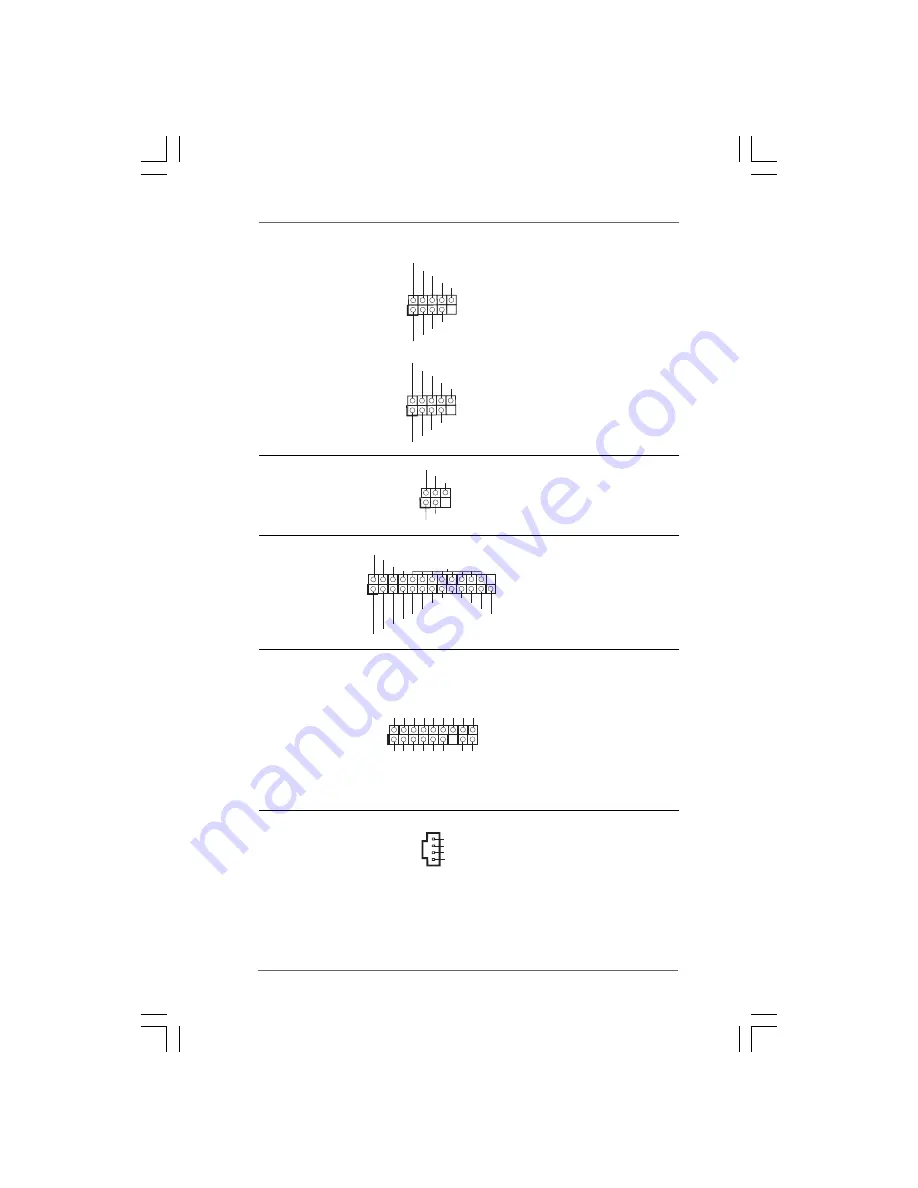
USB 2.0 Headers
Besides two default USB 2.0
(9-pin USB6_7)
ports on the I/O panel, there are
(see p.11 No. 19)
two USB 2.0 headers on this
motherboard. Each USB 2.0
header can support two USB
2.0 ports.
(9-pin USB4_5)
(see p.11 No. 20)
USB_PWR
USB_PWR
P+7
P-7
P+6
P-6
GND
GND
DUMMY
1
Infrared Module Header
This header supports an
(5-pin IR1)
optional wireless transmitting
(see p.11 No. 21)
and receiving infrared module.
DUMMY
GND
+5V
IRTX
IRRX
1
USB
_
P
W
R
USB
_
P
W
R
P
+
5
P
-
5
P
+4
P
-4
G
N
D
G
N
D
DU
MMY
1
Print Port Header
This is an interface for print
(25-pin LPT1)
port cable that allows
(see p.11 No. 22)
convenient connection of printer
devices.
1
AFD#
ERROR#
PINIT#
GND
SLIN#
STB#
SPD0
SPD1
SPD2
SPD3
SPD4
SPD5
SPD6
SPD7
ACK#
BUSY
PE
SLCT
Internal Audio Connectors
This connector allows you
(4-pin CD1)
to receive stereo audio input
(CD1: see p.11 No. 27)
from sound sources such as
a CD-ROM, DVD-ROM, TV
tuner card, or MPEG card.
CD-L
GND
GND
CD-R
CD1
TPM Header
This connector supports a
(17-pin TPM1)
Trusted Platform Module (TPM)
(see p.11 No. 7)
system, which can securely
store keys, digital certificates,
passwords, and data. A TPM
system also helps enhance
network security, protects
digital identities, and ensures
platform integrity.
1
GND
SMB_DATA_MAIN
LAD2
LAD1
GND
S_PWRDWN#
SERIRQ#
GND
PCICLK
PCIRST#
LAD3
+3V
LAD0
+3VSB
GND
FRAME
SMB_CLK_MAIN