


8
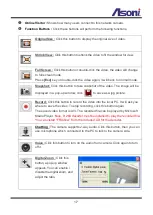
Microphone Input
Audio Output
I/O Connections
The terminal block inside of the camera also Digital Input and Relay Output. You can
connect the wires of connector to this terminal block to output these signals. The I/O
connector used in application, for e.g., motion detection, event triggering, alarm
notifications. It provides the interface to:
1 set of Digital Input (Alarm + GND) – The digital inputs for connecting devices
that can toggle between an open and closed circuit, such as PIRs, door/window
contacts, glass break detectors, etc. When a signal is received the status changes
and the input becomes active.
1 set of Relay Output (N.O. + COM or N.C + COM) – The output to Relay switch of
the alarm device such as LEDs, Sirens, etc.
Connects to an
microphone
Connects to an
amplified speaker
Содержание CAM649MA
Страница 12: ...11 B Monitor Setting 1 Right Click on the desktop Select Properties 2 Change color quality to Highest 32bit ...
Страница 16: ...15 1 2 3 4 5 When popup the following dialogue box click Yes ...
Страница 32: ...31 After set up click Apply to save the settings ...
Страница 36: ...35 C Network Setting Network Setting Network Setting ...


