AEU-7000-70V & AEU-7000
Implant / Surgery Systems
OPERATION
AND
MAINTENANCE
INSTRUCTION MANUAL
AEU-7000-70V System
Страница 1: ...AEU 7000 70V AEU 7000 Implant Surgery Systems OPERATION AND MAINTENANCE INSTRUCTION MANUAL AEU 7000 70V System...
Страница 2: ...the emissions requirements of IEC 60601 1 2 2001 09 These requirements provide reasonable protection against harmful electromagnetic interference in a typical medical installation However high levels...
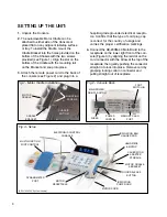
Страница 3: ...ation and maintenance of handpieces or other accessories for your unit PACKAGE CONTENTS Electronic Control Console P N 120330 AE 230M 40 Autoclavable Brushless Micromotor Autoclavable Motor Holder P N...
Страница 4: ...nsibilty of the user CAUTION All repairs are to be performed by authorized Aseptico service personnel only WARNING Always follow these guidelines when operating the unit Never touch drills burs or oth...
Страница 5: ...lution or sterile water Use only suitable irrigants as recommended by the implant manufacturer s instructions CAUTION Connect mains power cable to a properly grounded outlet only CAUTION The motor is...
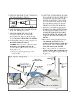
Страница 6: ...the proper certification markings 4 Connect the AE 230M 40 Motor Cord to the receptacle on the lower right front of the con sole Figure 3 by aligning the red dot on the cord connector with the arrow a...
Страница 7: ...nto the slot located on the front of the pump door c Grasp Luer connector and gently pull outwards then close and latch the pump door Slowly release tension on the Luer connector and allow the O Ring...
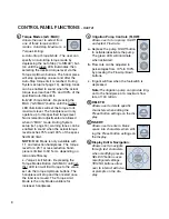
Страница 8: ...er and Integrated Calibration Program Allows user to calibrate the System to match the characteristics of the handpiece being used a Depress and release CAL button The System will run the selected han...
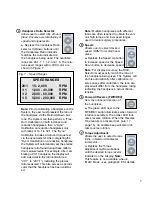
Страница 9: ...s been calibrat ed Fig 7 Speed Ranges SPEED RANGES 20 1 15 2 000 RPM 1 1 1 000 40 000 RPM 1 2 2 000 80 000 RPM 1 5 5 000 200 000 RPM Note Multiple handpieces with different ratios are often required t...
Страница 10: ...ction hand piece is limited to 60 N cm depending on ratio and efficiency c Torque Limit Mode Depressing the Torque Modes Button A S MAX until nei ther LED is lit will limit torque to the value set via...
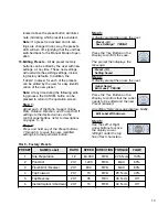
Страница 11: ...ill Reamer 20 1 Handpiece 800 RPM FWD MAX Torque Pump On 80 Flow Preset 4 Tap Forward 20 1 Handpiece 15 RPM FWD 25 N cm Torque Auto Stop Pump On 30 Flow Preset 5 Reverse Tap 20 1 Handpiece 35 RPM REV...
Страница 12: ...n specify an Auto Stop torque limit by de pressing the Auto Stop A S MAX button until the green LED illuminates then select ing the desired torque level The handpiece will stop operating one second af...
Страница 13: ...d torque characteristics inherent in MAX Torque Mode operation it is recommended that MAX Mode be used only for drilling procedures in osteotomy or surgical site preparation It is also recommended tha...
Страница 14: ...ndpieces NOTE Pressing Preset Button 3 at any time during the calibration process will exit the procedure however no calibration set tings will be saved into the System If either type of handpiece fai...
Страница 15: ...ttons refer to descriptions on pages 6 8 Step 2 Press and hold any of the Preset buttons 1 through 6 to save the new modified settings into that particular button Step 3 A display prompt then asks the...
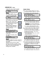
Страница 16: ...tem Setup menu press and hold the SETUP button for 1 second 15 The following prompt will be displayed Recall Factory Setup Press YES NO CANCEL a Press Yes to recall the factory setup menu The followin...
Страница 17: ...e out and become inactive Sleep Mode 1 15 2 30 3 Off CANCEL a To enable a 15 minute delay press 1 b To enable a 30 minute delay press 2 c To disable Sleep Mode Display stays on press 3 19 This prompt...
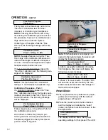
Страница 18: ...or The AEU 7000 70V will automatically sense the Foot Control and invoke the proper control software which allows dual functionality through either the key pad or foot switch Foot Pad Functions See Fi...
Страница 19: ...r the pedal is depressed Depress to gradually increase speed release to decrease speed b ON OFF Mode Foot pedal will switch the Motor On Off when depressed released approximately halfway Handle Instal...
Страница 20: ...card 4 Turn the Main Power Switch on the back panel On 5 The Display will show the following mes sage Press the Yes key on the Control Panel 6 The Display will then show the following message Press t...
Страница 21: ...olution and or sleeve the cord between each patient CONSOLE The exterior of the console may be cleaned by wiping with a soft cloth moistened with mild detergent or disinfecting solution SILICONE WATER...
Страница 22: ...ontainer seal is completely punctured Make sure the irrigation tubing is properly installed in pump door and flow is in the correct direction Replace worn tube section located under the pump door with...
Страница 23: ...umidity Limitation 1013 3 hPa 697 hPa 10 90 10 C 50 F 28 C 82 4 F SPECIFICATIONS Console Dimensions 9 98 W x 9 42 L x 5 10 H 25 3 cm x 23 9 cm x 12 9 cm Console Weight 7 3 lbs 3 3kg Power 100 240V 1 1...
Страница 24: ...r of such action In the event of alleged defect under warranty the purchaser is to notify Aseptico s Customer Service Department promptly Customer Service will provide instructions usually directing t...