


5.
12.
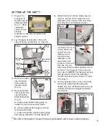
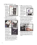
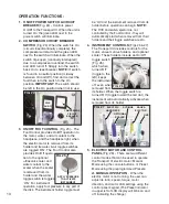
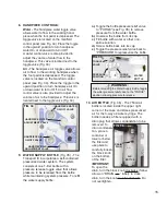
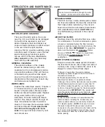
Fill the water-supply bottle with clean water or
other suitable irrigation fluid and attach to the
water bottle cap on the left side of the
air/electric module (Fig. 11a).
Optional Water-Supply Adapter
- Attach the
optional water-supply adapter (PN 330607) to
the end of the water bottle filter tube (Fig.
11b). Attach the opposite end of the Adapter
to the water supply. Toggle the water bottle
purge switch to the purge position.
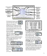
13.
On the back side of
the air/electric
module, rotate the
rear housing
downward 180°
(Fig. 12). (Note the
connector block in
the recess directly
below the rear
housing.)
14.
Disengage the locking tab on the handle.
Slowly and carefully lower the air/electric
module down until the rear housing
engages the connector block in the recess
below (Fig 13a). (
NOTE:
Ensure that the
three O-rings on the housing are lubricated
with an appropriate lubricant, preferably
containing PTFE. Dry O-rings will damage
the seals, resulting in poor performance.)
Lock the module into place by hand-
tightening the hold-down thumb-screw on
the housing, until snug (Fig 13b).
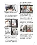
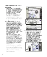
15.
Ensure that the lid on the waste container
is securely latched onto the container.
Hang the container onto the bracket
located on the back side of case lid (Fig.
14a). Plug the level-sensor cord connector
into the socket located on the motor
housing (Fig. 14b). The connector plug
and the socket are keyed and fit only in
one position. Gently press the connector
against the socket and rotate until the
connector aligns with and enters the
socket.
NOTE:
If the sensor is accidentally
unplugged, a warning beep will sound and
the compressor will automatically shut off.
16.
Attach the HVE and saliva ejector hose
connectors (white) to their respective ports
on the top of the waste tank (Fig. 15a, page
6). Note that the notches in the hose
connectors align to the white tabs on the
tank. Rotate the white locking latch over the
top of the two hose connectors to secure
them into position (Fig. 15b, page 6).
FIG. 11a
FIG. 11b
OPTIONAL
WATER
SUPPLY
ADAPTER
FIG. 12
CONN.
BLOCK
REAR
HOUSING
FIG. 13a
FIG. 13b
HOLD-DOWN
SCREW
CONNECTOR
FIG. 10
FOOT CONTROL
CONNECTOR
FIG. 14a
FIG. 14b
SENSOR
CORD
BRACKET
WASTE
TANK
Содержание AEU-525 Transport III
Страница 1: ...OPERATION MAINTENANCE MANUAL AEU 525 AEU 525S Portable Dental System Transport III...
Страница 30: ...28 NOTES...
Страница 31: ...29 NOTES...