


Installation & Maintenance Instructions
2-WAY INTERNAL PILOT-OPERATED SOLENOID VALVES
NORMALLY CLOSED OPERATION - ¾” , 1” , 1¼” , 1½” OR 2” NPT
FUEL GAS SERVICE
Temperature Limitations
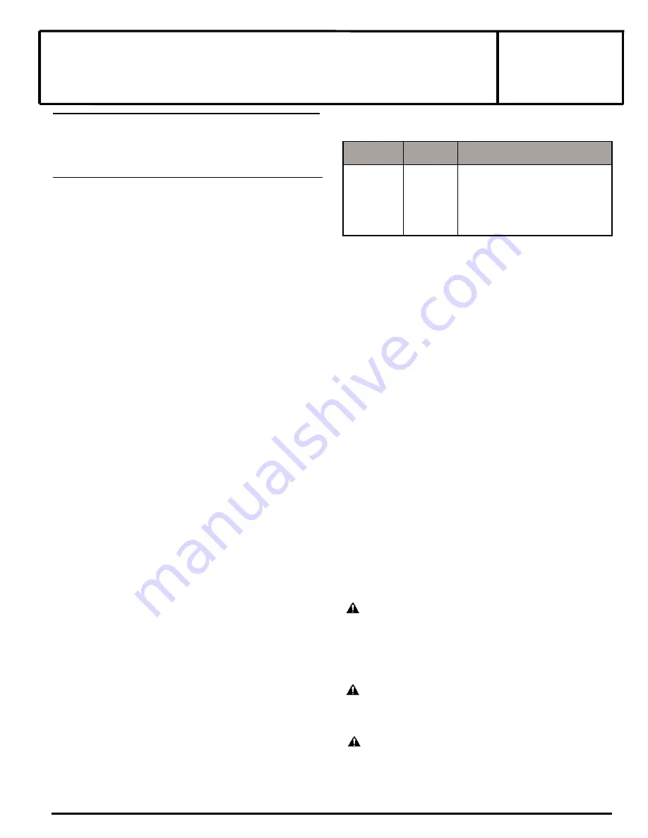
For valve ambient and fl uid temperatures, refer to chart
SERIES
8214(200)
NOTICE: See separate solenoid installation and maintenance
instructions for information on: Wiring, Solenoid Temperature,
Causes of Improper Operation, and Coil Replacement.
For exploded views, see I&M No. V9565R3 - Section 2.
DESCRIPTION
Series 8214(200) valves are 2-way normally closed diaphragm-
type solenoid valves designed for fuel gas service. Valve bodies
are made of rugged aluminum with trim and internal parts made
of steel and stainless steel. Series 8214 (200) valves maybe
provided with a watertight solenoid with a watertight junction box
depending upon basic valve construction.
The valves feature mounting fl anges on the inlet and outlet of the
valve. These fl anges allow like valves to be mounted together in
series without the use of an intermediate pipe nipple. This feature is
intended for applications where two redundant valves are required
by a governing body. The mounting of the two valves in
series is accomplished with an optional connecting hardware kit.
Please see additional instructions for the use of this kit in the Piping
section of this I&M sheet.
Valve catalog numbers with Suffi x C have an integral electrical and
visual position indicator and proof of closure construction. Valves
with Suffi x VI (in the catalog number)have a visual only position
indicator. The position indicator gives visual indication of Open
and Shut positions by means of a small ball. The ball travels up
and down in a transparent holder between labels Open and Shut.
Electrical indication is accomplished by the operation of a single
pole single throw reed switch. Reed switch contact is closed when
solenoid is de-energized; open when energized.
Note: Position indicators not available for DC valves.
Provisions for Pressure and Seat Leakage Testing
(See Figure 1.)
Series 8214 (200) valves are provided with four 1/8” NPT
tapped and plugged holes, two on either side of valve body. Two
upstream for pressure testing; two downstream for seat leakage
testing. Leakage testing frequency shall be at least annually
in accordance with NFPA-86 or original equipment manufacturer
recommendations. Testing is also required after valve disassembly
and reassembly for inspection, cleaning or rebuilding.
OPERATION
Normally Closed:
Valve is closed when solenoid is de-energized;
open when energized.
Operating Pressure Differential
Minimum 0 psig
Maximum 5 psig
INSTALLATION
Check nameplate for correct catalog number, pressure, voltage,
frequency and service. Never apply incompatible fl uids or
exceed pressure rating of the valve. Installation and valve
maintenance to be performed by qualifi ed personnel.
I&M No. V 9565_Sec1 R3
*Includes catalog numbers with or without Suffi x C or VI
Positioning
Catalog Numbers 8214G236, 251, 261, 266, 271, 276, 281
without Suffi x C or VI can be mounted with solenoid in any
Position horizontal and above.
All catalog Numbers with Suffi x C or VI must be mounted with
solenoid in the vertical-upright position
Piping
Connect piping to valve according to markings on valve body. Apply
pipe compound sparingly to male pipe threads only. If applied to
valve threads, the compound may enter the valve and cause
operational diffi culty. Avoid pipe strain by properly supporting
and aligning piping. When tightening the pipe, do not use valve
or solenoid as a lever. Locate wrenches applied to valve piping as
close as possible to connection point. Locate wrenches applied to
valve body per Figure 1. Valve should be checked for external
leakage at piping connections after installation, see Testing for
External Leakage section.
These valves feature mounting fl anges on the inlet and outlet of the
valve for direct connection to one another or connection in a valve
train with an optional Flange Adapter Kit. The optional Flange
Adapter Kit may also be used in place of direct piping for easy
maintenance and disassembly of the valve without breaking
any NPT pipe connections. This feature may only be used with
an optional ASCO connecting hardware kit containing approved
hardware and seals. The use of hardware and seals that are not part
of the kit will void your warranty. Please refer to Installation &
Maintenance Instructions, I&M No. V9567 for kit part numbers
and contact ASCO for availability.
WARNING: To prevent the possibility of death,
serious injury or property damage, only use the
optional ASCO connecting hardware kit for the
direct connection of these valves to one another.
Complete instructions and guidelines for piping
the valves together are included with the kit.
CAUTION: TO avoid damage to the valve body, DO
NOT OVERTIGHTEN PIPE CONNECTIONS. If PTFE tape,
paste, spray or similar lubricant is used, use extra care
when tightening due to reduced friction.
CAUTION: TO protect the solenoid valve, install
a strainer or fi lter, suitable for the service involved, in
the inlet side as close to the valve as possible. Clean
periodically depending on service conditions. See ASCO
series 8600 and 8602 for strainers.
Page 1 of 7
ASCO Valves®
©ASCO Valve, Inc.
50 Hanover Road, Florham Park, New Jersey 07932 www.ascovalve.com
All Rights Reserved.
E248536 - 09/14
I&M No. V 9565_Sec 1 R3
Catalog
Numbers*
Insulation
Class
Minimum and Maximum Ambient and
Fluid Temperatures
8214G236
8214G251
8214G261
8214G266
8214G271
8214G276
8214G281
F
H
-40 °F (-40 °C) to 125 F (52 °C)
-40 °F (-40 °C) to 140 F (60 °C)


