Input Impedance
Balanced 20 Kohms
Unbalanced 10 Kohms
Input Headroom
+ 21 dB
CMRR
>45 dB, 20 Hz—20 KHz
Output Impedance
Balanced 300 ohms
Unbalanced 150 ohms
Output Level (Max)
+ 21dB
Frequency Response
30Hz—20KHz±0.5dB
Note:
30 Hz is a function
of the High Pass filter
Signal to Noise ratio
(Controls at Unity)
-90 dB Unweighted
-93 dB ‘A’ weighted
Distortion
.004% THD,0dB,1KHz
Dynamic Range
111 dB
Power Requirements
100/120 V AC
220/240 V AC
Weight
5 lbs/2.2 Kg
Dimensions
19"W x 1
3
/
4
"H x 6"D
482 x 44 x 155mm
Input Connector type
XLR, Balanced Jack
Output Connector type
XLR
Crossover point frequencies
are changed internally by
varying the value of 4 resis-
tors per channel. Full details
are in the Service Notes sec-
tion of the Owner's Manu-
al, and are also printed in-
side the lid.
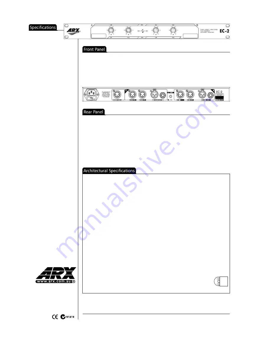
• Balanced XLR Inputs
and
Outputs
• Additional summed mono Low output
• 2 way/3 way mode switch
• Low and High Output controls for 2 way mode
• Low, Mid and High Output controls for 3 way
mode
The crossover shall be a dual channel 2 way
or single channel 3 way unit in a steel chas-
sis six inches deep and one rack unit high.
There shall be a rear panel switch to put
the unit into either mode. The crossover
shall have true Linkwitz Riley 24 dB per oc-
tave, phase corrected state variable filters.
The front panel shall feature controls for
Low and High frequencies in dual channel
mode, and Low, Mid and High frequencies
in single channel mode.
There shall be corresponding outputs on the
rear panel, plus a separate mono low fre-
quency summed output. Each output will
have up to +6dB of gain available, to com-
pensate for amplifiers and speakers of dif-
fering sensitivities. There shall also be a pre-
set 30 Hz High Pass filter to remove unwant-
ed subsonics.
The unit shall have electronically Balanced
inputs, on TipRingSleeve (TRS) jack connec-
tors (Tip +, Ring -, Sleeve Ground), and XLR
connectors, with passive RFI filters and an
Input impedance of 20 Kohms (10 Kohms
unbalanced). The Outputs shall also be Bal-
anced, on XLR connectors, with an output
impedance of 300 ohms balanced (150 ohms
unbalanced),
The Input headroom shall be +21dB, with a
CMRR of better than 50dB, and the frequen-
cy response shall be 30 Hz, -0.5dB (as a func-
tion of the High Pass filter) to 20 KHz,
+0.16dB, and the maximum Output level shall
be +21dB, with a Signal to Noise ratio of -
93dB ‘A’ weighted (-90dB unweighted).
Total Harmonic Distortion shall be .004% @
0dB, 1 KHz, and the unit shall have a dynam-
ic range of 111dB.
AC Power shall be supplied via a removable
mains cable, connecting to an IEC connector
with an integral fuse and voltage change
switch on the unit’s rear panel.
The crossover shall be the ARX EC-2
• Marker panels for labelling crossover assigns
• 2 way/3 way status LEDs
Our policy is one of continuous im-
provement, and therefore designs
may change without notice. Howev-
er, unless otherwise stated, specifi-
cations will always equal or exceed
those previously given.
• AC input connector, with voltage switch and
fuse.
ARX Systems are based in Melbourne, Australia, where all ARX Products are assem-
bled and tested in our ‘state-of-the-art’ manufacturing facility
For over 20 years ARX has designed, manufactured and supported Audio Products for
Professional users and applications worldwide
©2003 ARX Systems Pty. Ltd. ACN 006 471 825. All rights reserved. ARX Systems® is a Registered Trade Mark
ARX Systems Pty Ltd; PO Box 15, Moorabbin, Victoria 3189, Australia
Phone: 03 9555 7859 Fax: 03 9555 6747 International Fax +61 3 9555 6747
Email: [email protected] Internet: www.arx.com.au
Specifications available on CD ROM
Latest updates always available on the ARX website - www.arx.com.au


