Controls, Indicators, and Connectors
SharpSwitch™ PCIE-9205 Installation and Use (6806800U18D)
49
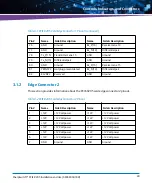
3.1.2
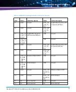
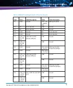
Edge Connector 2
This section provides information about the PCIE-9205 card edge connector 2 pinout.
76
GND
Ground
Rx_P(14)
Receiver Lane 14
77
GND
Ground
Rx_N(14)
Differential pair
78
Tx_P(15)
Transmitter Lane 15
GND
Ground
79
Tx_N(15)
Differential pair
GND
Ground
80
GND
Ground
Rx_P(15)
Receiver Lane 15
81
PRSNT#2
Hot plug present detect
Rx_N(14)
Differential pair
82
RSVD#2
Reserved
GND
Ground
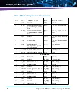
Table 3-1 PCIE-9205 Card Edge Connector 1 Pinout (continued)
Pin #
Name
Side B Description
Name
Side A Description
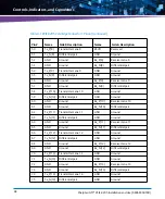
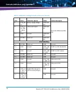
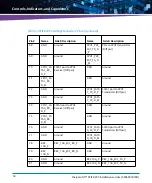
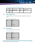
Table 3-2 PCIE-9205 Card Edge Connector 2 Pinout
Pin #
Name
Side B Description
Name
Side A Description
1
+12V
+12 Volt power
+12V
+12 Volt power
2
+12V
+12 Volt power
+12V
+12 Volt power
3
+12V
+12 Volt power
+12V
+12 Volt power
4
+12V
+12 Volt power
+12V
+12 Volt power
5
+12V
+12 Volt power
+12V
+12 Volt power
6
+12V
+12 Volt power
+12V
+12 Volt power
7
GND
Ground
GND
Ground
Содержание SharpSwitch PCIE-9205
Страница 1: ...SharpSwitch PCIE 9205 Installation and Use P N 6806800U18D March 2018 ...
Страница 6: ...SharpSwitch PCIE 9205 Installation and Use 6806800U18D 6 Contents ...
Страница 8: ...SharpSwitch PCIE 9205 Installation and Use 6806800U18D 8 List of Tables ...
Страница 10: ...SharpSwitch PCIE 9205 Installation and Use 6806800U18D 10 List of Figures ...
Страница 22: ...SharpSwitch PCIE 9205 Installation and Use 6806800U18D Safety Notes 22 ...
Страница 30: ...SharpSwitch PCIE 9205 Installation and Use 6806800U18D Sicherheitshinweise 30 ...
Страница 44: ...Hardware Preparation and Installation SharpSwitch PCIE 9205 Installation and Use 6806800U18D 44 ...
Страница 62: ...Controls Indicators and Connectors SharpSwitch PCIE 9205 Installation and Use 6806800U18D 62 ...
Страница 68: ...Functional Description SharpSwitch PCIE 9205 Installation and Use 6806800U18D 68 ...
Страница 86: ...BIOS SharpSwitch PCIE 9205 Installation and Use 6806800U18D 86 ...
Страница 101: ......


