FRU Installation
AXP640 Installation and Use (6806800M24F
)
162
6.6.2
Installing an FTM
Installation Procedure
1. While supporting the FTM, align the FTM carefully into the fan guide rails in the
shelf and slowly slide the FTM until the it is flush with the chassis.
2. Tighten the four chassis retention screws to secure the FTM. The recommended
torque settings is 3.5 inch-pounds.
When the red LED turns off and the green LED turns on, the fan is operating.
6.7
Replacing the Fan Filter
Your replacement fan filter consists of a filter media for the fan bezel, and a smaller media for
the inlet region adjacent to the SAMs.
Air filters should be checked occasionally to make sure they are not obstructed or damaged.
Visually inspect filters for tears or rips. Do not reinstall a torn filter as it will be ineffective in
trapping particulates and will interrupt air flow distribution. To maintain safety certification,
use only Artesyn approved fan filters. You can order replacement fan filters (part number
RAF640) by contacting your Artesyn sales representative. For detailed information on filter
maintenance and cleaning, see
.
Replacement Procedure
To replace the fan filter, follow these steps. Please have your replacement fan filter available
before starting this procedure.
Main Filter Replacement Procedure
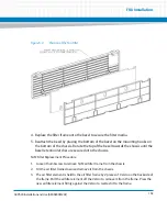
1. Remove the front bezel by squeezing the retention clasps incorporated into the top
corners of the bezel and rotating the top of the bezel away from the chassis.
2. Place the bezel face down so that the filter media and metal frame are facing up,
and rotate the filter frame away from the housing.
3. Insert the replacement fan filter on the bezel by aligning the oval cutouts in the
filter material with the light-pipe ovals.
Содержание AXP640
Страница 1: ...AXP640 Installation and Use P N 6806800M24F May 2014 ...
Страница 8: ...AXP640 Installation and Use 6806800M24F Contents 8 Contents Contents ...
Страница 10: ...AXP640 Installation and Use 6806800M24F 10 List of Tables ...
Страница 50: ...Platform Architecture AXP640 Installation and Use 6806800M24F 50 ...
Страница 53: ...AXP640 Shelf Description AXP640 Installation and Use 6806800M24F 53 Figure 2 2 DC Rear Shelf View ...
Страница 69: ...AXP640 Shelf Description AXP640 Installation and Use 6806800M24F 69 Figure 2 13 AC Inlet Markings 110V ...
Страница 70: ...AXP640 Shelf Description AXP640 Installation and Use 6806800M24F 70 Figure 2 14 AC Inlet 220V ...
Страница 77: ...AXP640 Shelf Description AXP640 Installation and Use 6806800M24F 77 Figure 2 18 DC Rating Label ...
Страница 78: ...AXP640 Shelf Description AXP640 Installation and Use 6806800M24F 78 Figure 2 19 AC Rating Label ...
Страница 90: ...Site Preparation AXP640 Installation and Use 6806800M24F 90 Figure 3 2 ETSI Frame Mount Rear View ...
Страница 91: ...Site Preparation AXP640 Installation and Use 6806800M24F 91 Figure 3 3 ETSI Frame Mount Side View ...
Страница 92: ...Site Preparation AXP640 Installation and Use 6806800M24F 92 Figure 3 4 19 inch Frame Front Mount Front View ...
Страница 93: ...Site Preparation AXP640 Installation and Use 6806800M24F 93 Figure 3 5 19 inch Frame Mid mount Front View ...
Страница 94: ...Site Preparation AXP640 Installation and Use 6806800M24F 94 Figure 3 6 19 23 inch Frame Mid mount Side View ...
Страница 95: ...Site Preparation AXP640 Installation and Use 6806800M24F 95 Figure 3 7 23 inch Frame Front Mount Front View ...
Страница 101: ...Site Preparation AXP640 Installation and Use 6806800M24F 101 Figure 3 13 Planning Checklist 2 ...
Страница 102: ...Site Preparation AXP640 Installation and Use 6806800M24F 102 ...
Страница 112: ...AXP640 Operations AXP640 Installation and Use 6806800M24F 112 ...
Страница 136: ...AXP640 Shelf Installation AXP640 Installation and Use 6806800M24F 136 ...
Страница 164: ...FRU Installation AXP640 Installation and Use 6806800M24F 164 ...
Страница 186: ...Shelf Management Alarm Module AXP640 Installation and Use 6806800M24F 186 ...
Страница 189: ......


