AXP640 Operations
AXP640 Installation and Use (6806800M24F
)
104
cannot be switched on while you are working.
3. Connect the AC International Electric Code (IEC) wired connector to the AC power
supplies.
4.2.2
DC System Startup Procedure
Procedure
Depending on the system configuration, the actual powering up may take up to 3 minutes.
Make sure that the system has been placed in a location at room temperature for at least 24
hours before powering it up.
1. Mount the grounding cable to the Protective Earth connection lug if not done
already.
2. Set the breakers on the PEM face plates to the OFF (tripped) position if they are not
already in this position.
3. Make sure that the external power feeds you plan to attach are powered off and
cannot be switched on while you are working.
4. Attach the power cables with 2 hole lugs to the DC power inlet in the rear of the
shelf.
5. Energize the power feeds at the external device.
6. Push the DC PEM breakers to the ON position.
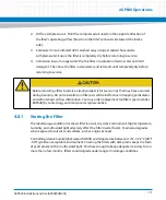
Ensure that the DC and DC return are connected correctly. Applying reversed power causes
damage to the electrolytic capacitors of the filter
Содержание AXP640
Страница 1: ...AXP640 Installation and Use P N 6806800M24F May 2014 ...
Страница 8: ...AXP640 Installation and Use 6806800M24F Contents 8 Contents Contents ...
Страница 10: ...AXP640 Installation and Use 6806800M24F 10 List of Tables ...
Страница 50: ...Platform Architecture AXP640 Installation and Use 6806800M24F 50 ...
Страница 53: ...AXP640 Shelf Description AXP640 Installation and Use 6806800M24F 53 Figure 2 2 DC Rear Shelf View ...
Страница 69: ...AXP640 Shelf Description AXP640 Installation and Use 6806800M24F 69 Figure 2 13 AC Inlet Markings 110V ...
Страница 70: ...AXP640 Shelf Description AXP640 Installation and Use 6806800M24F 70 Figure 2 14 AC Inlet 220V ...
Страница 77: ...AXP640 Shelf Description AXP640 Installation and Use 6806800M24F 77 Figure 2 18 DC Rating Label ...
Страница 78: ...AXP640 Shelf Description AXP640 Installation and Use 6806800M24F 78 Figure 2 19 AC Rating Label ...
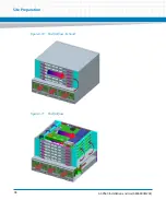
Страница 90: ...Site Preparation AXP640 Installation and Use 6806800M24F 90 Figure 3 2 ETSI Frame Mount Rear View ...
Страница 91: ...Site Preparation AXP640 Installation and Use 6806800M24F 91 Figure 3 3 ETSI Frame Mount Side View ...
Страница 92: ...Site Preparation AXP640 Installation and Use 6806800M24F 92 Figure 3 4 19 inch Frame Front Mount Front View ...
Страница 93: ...Site Preparation AXP640 Installation and Use 6806800M24F 93 Figure 3 5 19 inch Frame Mid mount Front View ...
Страница 94: ...Site Preparation AXP640 Installation and Use 6806800M24F 94 Figure 3 6 19 23 inch Frame Mid mount Side View ...
Страница 95: ...Site Preparation AXP640 Installation and Use 6806800M24F 95 Figure 3 7 23 inch Frame Front Mount Front View ...
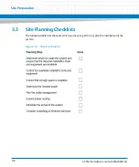
Страница 101: ...Site Preparation AXP640 Installation and Use 6806800M24F 101 Figure 3 13 Planning Checklist 2 ...
Страница 102: ...Site Preparation AXP640 Installation and Use 6806800M24F 102 ...
Страница 112: ...AXP640 Operations AXP640 Installation and Use 6806800M24F 112 ...
Страница 136: ...AXP640 Shelf Installation AXP640 Installation and Use 6806800M24F 136 ...
Страница 164: ...FRU Installation AXP640 Installation and Use 6806800M24F 164 ...
Страница 186: ...Shelf Management Alarm Module AXP640 Installation and Use 6806800M24F 186 ...
Страница 189: ......


