


Connectors, LEDs, and Switches
MVME8100 / MVME8110 Installation and Use (6806800P25J
)
78
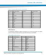
3.2.1
On-board LEDs
The on-board LEDs are listed below. The LEDs are located on the rear side of the board just
opposite of the battery location. To view the board, see
3.3
Switches
The board provides the following configuration switches:
S2 Switch
S3 Switch
S4 Switch
S5 Switch
Reset/Abort Switch
Table 3-15 On-board LEDs Status
Label
Function
Color
Description
D32
MMC Write Protect
off
WP disabled
Green
WP enabled
D33
ENP1: PS1_LED_N
ENP4: Board FAIL
Amber
D34
ENP1: PS2_LED_N
ENP4: POWER
Green
D35
ENP1: PS3_LED_N
ENP4: RESET
Amber
D19
USR_LED2_N
Red
USR_LED3_N
Yellow
Содержание MVME8100
Страница 1: ...MVME8100 MVME8110 Installation and Use P N 6806800P25J August 2015 ...
Страница 8: ...MVME8100 MVME8110 Installation and Use 6806800P25J 8 List of Tables ...
Страница 10: ...MVME8100 MVME8110 Installation and Use 6806800P25J 10 List of Figures ...
Страница 26: ...MVME8100 MVME8110 Installation and Use 6806800P25J Sicherheitshinweise 26 ...
Страница 58: ...Hardware Preparation and Installation MVME8100 MVME8110 Installation and Use 6806800P25J 58 ...
Страница 84: ...Connectors LEDs and Switches MVME8100 MVME8110 Installation and Use 6806800P25J 84 ...
Страница 108: ...Functional Description MVME8100 MVME8110 Installation and Use 6806800P25J 108 ...
Страница 122: ...Related Documentation MVME8100 MVME8110 Installation and Use 6806800P25J 122 ...
Страница 123: ......


