


AT32F435/437
Series Reference Manual
2022.11.11
Page 247
Rev 2.03
14.1 Basic timer (TMR6 and TMR7)
14.1.1 TMR6 and TMR7 introduction
Each of the basic timers (TMR6 and TMR7) includes a 16-bit up counter and the corresponding control
logic. without being connected to external I/Os, they can be used for a basic timing and providing clocks
for the digital-to-analog converter (DAC).
14.1.2 TMR6 and TMR7 main features
16-bit up counter, reload
16-bit prescaler used to divide the TMR_CLK frequency by any factor between 1 and 65536
Synchronization circuit to trigger DAC (Unique characteristics)
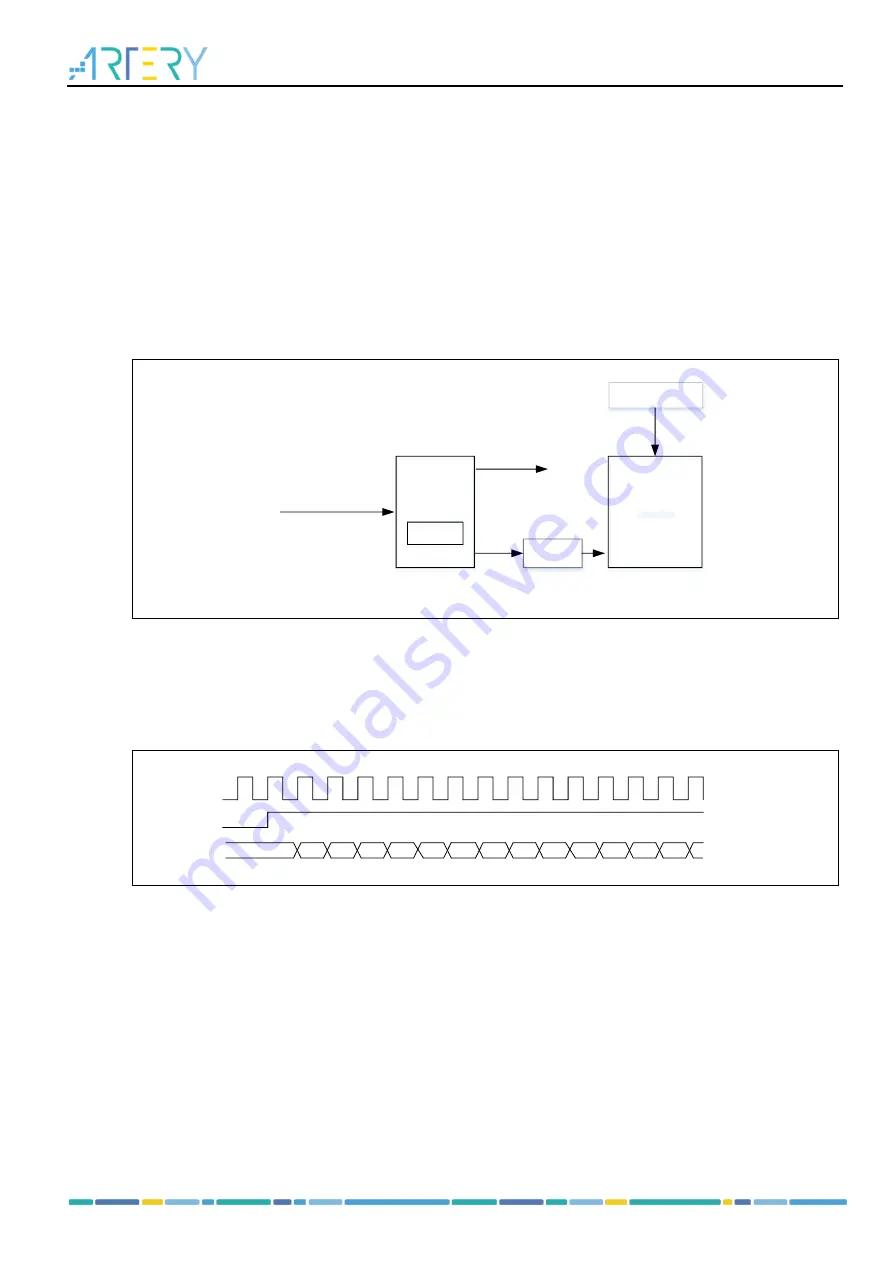
Figure 14-1Basic timer block diagram
TMRxCLK from CRM
Reset, Enable, Count
DIV
prescaler
counter
Trigger
controller
Controller
TRGOUT
To DAC
Period
register
14.1.3 TMR6 and TMR7 function overview
14.1.3.1 Count clock
The counter clock of TMR6 and TMR7 is provided by the internal clock source (CK_INT) divided by
prescaler.
Figure 14-2 Control circuit with CK_INT divided by 1
CK_INT
TMREN
COUNTER
12
11
13
14
15
16
00
01
02
03
04
05
06
07
14.1.3.2 Counting mode
The basic timer only supports upcounting mode, and it has an internal 16-bit counter.
The TMRx_PR register is used to set the counting period. The The value in the TMRx_PR is immediately
moved to the shadow register by default. When the periodic buffer is enabled (PRBEN=1), the value in
the TMRx_PR register is transferred to the shadow register only at an overflow event.
The TMRx_DIV register is used to set the counting frequency. The counter counts once every count
clock period (DIV[15:0]+1). Similar to the TMRx_PR register, when the periodic buffer is enabled, the
value in the TMRx_DIV register is updated to the shadow register at an overflow event.
Reading the TMRx_CNT register returns to the current counter value, and writing to the TMRx_CNT
register updates the current counter value to the value being written.
An overflow event is generated by default. Set OVFEN=1 in the TMRx_CTRL1 to disable generation of
update events. The OVFS bit in the TMRx_CTRL1 register is used to select overflow event source. By
default, counter overflow/underflow, setting OVFSWTR bit and the reset signal generated by the slave
timer controller in reset mode trigger the generation of an overflow event. When the OVFS bit is set, only


