Arista MicroBox-7824B-E01 Скачать руководство пользователя страница 1

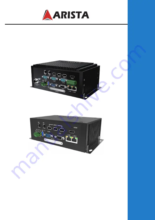
This manual is a user guide for Microbox-7824B E-Series Fanless 
Industrial MicroBox Computer. It includes detailed description about how 
to install and operate the product. Arista Corporation recommends users to 
read through the entire manual and follow instructions to avoid any kind of 
obscurity in using the product. For any questions or support, please call us 

at 1.877.827.4782 Monday through Friday 8:00am to 5:00PM Pacific Time.


USER  MANUAL 

Talk to us. We listen.

MicroBox-7824B E-Series Fanless Industrial MicroBox Computer

                 MicroBox-7824B-E01    MicroBox-7824B-E02    
                

Содержание MicroBox-7824B-E01

Страница 1: ...rporation recommends users to read through the entire manual and follow instructions to avoid any kind of obscurity in using the product For any questions or support please call us at 1 877 827 4782 Monday through Friday 8 00am to 5 00PM Pacific Time USER MANUAL Talk to us We listen MicroBox 7824B E Series Fanless Industrial MicroBox Computer MicroBox 7824B E01 MicroBox 7824B E02 ...

Страница 2: ...d with this unit For any reason a different power cord is used it should be certified by local and national standards and used under guidance of authorized technician Never use a faulty power cord with this unit Please contact the manufacturer or nearest authorized repair service right away for a replacement if damaged power cord is received The power supply cord is used as the main disconnect dev...

Страница 3: ...e MicroBox computer 19 Connecting to display 23 Connecting to touch screen 24 Connecting to keyboard or mouse 24 Connecting to network 25 Connecting the power supply 26 Connecting the battery power only for MicroBox 7824B E01 28 Installing memory module expansion card 29 Chapter 4 BIOS Setup 32 Introduction 32 Entering the setup 33 Main Menu 35 Advanced Menu 36 Chipset Menu 43 Security Menu 46 Boo...

Страница 4: ...a fanless operation This improves computer speed while minimizing movements on the internal components of MicroBox 7824B E Series Introduction Applications Office electronics Instrumentation and measuring equipment Machine tools Audiovisual equipment Home appliances Communication equipment other than trunk lines Do not use the products covered herein for the following equipment that demands extrem...

Страница 5: ...up to four USB ports Intel Gen7 Intel Graphics DX 11 OGL3 2 supports display resolution up to 1920 1080 Supports up to four serial ports for MicroBox 7824B E01 and all the serial ports COM1 COM4 can be configured to RS 232 RS 422 or RS 485 mode in BIOS setup Build in expansion connectors CFAST Card slot MINI PCIE slot the MINI PCIE slot supports Wi Fi function and Solid State Drives SSD Supports p...

Страница 6: ...ort for MicroBox 7824B E01 LAN 2 x Gigabit Keyboard Mouse 1x PS2 keyboard 1x PS2 mouse Power 1x DC IN power 1 x Battery power input for MicroBox 7824B E01 Operating system OS Support Windows 7 up Physical information Mounting Wall mounting DIN Rail mounting Physical dimension MicroBox 7824B E01 8 84 X 3 47 X 5 53 inch 224 4 X 88 1 X 140 5 mm L X H X D MicroBox 7824B E02 7 71 X 2 50 X 4 59 inch 195...

Страница 7: ...ect items carefully to make sure no item is damaged and all items listed are present in your package t ures MicroBox 7824B E01 x1 MicroBox 7824B E02 x1 Unpacking AC power cable x1 DIN Rail AC DC power supply x1 DC power cable x1 ...

Страница 8: ...8 Product overview Chapter 2 Basics Rear Right Top Left Bottom Front MicroBox 7824 E01 ...

Страница 9: ...rt Speed LED Activity LED LED Indications on the LAN port Status Description Activity LED Off No network connection On Data transmission activity Speed LED Off Data transmission at the rate of 10Mbps Orange Data transmission at the rate of 1Gbps Green Data transmission at the rate of 100Mbps PWR LED Power LED indicator The LED lights up when you turn on the system and switches off in standby mode ...

Страница 10: ...10 Rear Right Top Left Front MicroBox 7824 E02 ...

Страница 11: ...ty LED LED Indications on the LAN port Status Description Activity LED Off No network connection On Data transmission activity Speed LED Off Data transmission at the rate of 10Mbps Orange Data transmission at the rate of 1Gbps Green Data transmission at the rate of 100Mbps PWR LED Power LED indicator The LED lights up when you turn on the system and switches off in standby mode HDD LED Hard Disk A...

Страница 12: ...ustrial microbox computer Top View Physical dimension MicroBox 7824B E01 L Overall length H Overall height D Overall width Weight 8 84 224 4mm 3 47 88 1mm 5 53 140 5 mm 5 1 lb 2 3 kg 108 0 mm 4 25 140 5 mm 5 53 224 4 mm 8 84 212 6 mm 8 37 Front View 201 4 mm 7 93 88 1 mm 3 47 MicroBox 7824 E01 ...

Страница 13: ... 116 5 mm 4 59 195 8mm 7 71 185 0 mm 7 28 Front View 173 0 mm 6 81 63 5 mm 2 50 MicroBox 7824 E02 MicroBox 7824B E02 L Overall length H Overall height D Overall width Weight 7 71 195 8mm 2 50 63 5mm 4 59 116 5 mm 4 4lb 2 0 kg ...

Страница 14: ... of MicroBox 7824B E01 microbox computer Connectors are located on the front panel of MicroBox 7824B E02 microbox computer Chapter 3 Connections This section describes connections connectors available on MicroBox 7824B E Series microbox computer ...

Страница 15: ...485 2 RXD Receive data TX Transmit data RS 422 RS 485 3 TXD Transmit data RX Receive data RS 422 4 DTR Data terminal ready RX Receive data ground RS 422 5 GND Signal ground GND Signal ground 6 DSR Data set ready N C 7 RTS Request to send N C 8 CTS Clear to send N C 9 Ring IN Ring indicator N C Note COM1 COM4 ports can be set to RS 232 mode default RS 422 mode or RS 485 Mode ...

Страница 16: ... VGA Green signal 3 VGA B VGA Blue signal 4 NC No connection 5 GND Ground 6 GND Ground 7 GND Ground 8 GND Ground 9 NC No connection 10 GND Ground 11 NC No connection 12 CRT DDC Data The data of display data channel 13 VGA HS VGA H Sync signal 14 VGA VS VGA V Sync signal 15 CRT DDC Clock The clock of display data channel 1 ...

Страница 17: ... GPIO output 4 I O_BUS_GPIO3 GPIO input 5 I O_BUS_GPIO4 GPIO output 6 I O_BUS_GPIO5 GPIO input 7 I O_BUS_GPIO6 GPIO output 8 I O_BUS_GPIO7 GPIO input 9 I O_BUS_GPIO8 GPIO output 10 GND Ground GPIO settings Input Ouput I O_BUS_GPIO1 GPIO42 0xFFF240 bit2 I O_BUS_GPIO2 GPIO71 0xFFF270 bit1 I O_BUS_GPIO3 GPIO50 0xFFF250 bit0 I O_BUS_GPIO4 GPIO16 0xFFF210 bit6 I O_BUS_GPIO5 GPIO52 0xFFF250 bit2 I O_BUS...

Страница 18: ...18 Pins in the DC IN power connector 2 Pin NO Definition 1 GND 2 24V Pin NO Definition 1 24V 2 GND 1 Or ...

Страница 19: ...to a wall or board you will require the mounting screws found in the accessory box Please follow the steps shown in the diagram below Step1 Situate the four 8 32UNC size screws on a board or a wall and use a screwdriver to firmly fix them into the wall or board Do not completely tighten the screws Step2 Then put the MicroBox 7824B E Series microbox computer onto the screws through the mounting hol...

Страница 20: ...ter is correctly and securely seated onto the board or wall Screw tightened It is very important to place the unit in a suitable environment Make sure the area is well ventilated out of direct sunlight away from sources of excessive dust dirt heat water moisture and vibration ...

Страница 21: ...tal clasp Metal clasp Step1 Place the metal clasp on the back of the MicroBox 7824B E Series microbox computer and screw it in using 6 32UNC sized screws Step2 Place one Din Rail on the wall or board and use a screwdriver to tighten the screws to affix the Din Rail onto the wall or board Wall or board Din Rail ...

Страница 22: ...tep4 You can also slide the metal clasp around the Din rail to move the computer to a desired position To remove the MicroBox 7824B E Series industrial microbox computer from Din rail press down the two iron loop springs built in the metal clasp down on the rail to loose it then remove the MicroBox 7824B E Series from the rail ...

Страница 23: ...rt of the MicroBox 7824B E Series fanless industrial microbox computer Connect the other end of the VGA cable to the VGA port of a display Connect one end of the HDMI cable to the HDMI port of the MicroBox 7824B E Series fanless industrial microbox computer Connect the other end of the HDMI cable to the HDMI port of a display 1 Connecting to a display through VGA port 2 Connecting to a display thr...

Страница 24: ...oBox 7824B E Series industrial computer Figure 2 Connecting to touch screen MicroBox 7824B E01 USB port USB port Serial port COM1 COM4 Display Serial data cable not supplied USB cable not supplied Connect one end of the USB cable not supplied or serial data cable not supplied to the USB port or serial port COM1 COM4 port of the MicroBox 7824B E Series fanless industrial microbox computer Connect t...

Страница 25: ... mouse jack Modem Connecting to network Connect one end of the RJ45 LAN cable to the LAN port of the MicroBox 7824B E Series computer Connect the other end of the RJ45 LAN cable to the LAN port of a modem LAN port LAN port RJ45 LAN cable not supplied MicroBox 7824B E01 ...

Страница 26: ...microbox computer Connect the other end of 72W DIN Rail AC DC power supply to an AC outlet Connect Power and Cable 8 Important Before you use the power supply correctly and securely connect the supplied AC power cable to the terminal of L for live wire N for neutral wire and Ground on the power supply and connect the supplied DC power cable to the Power and Ground terminals AC power cable supplied...

Страница 27: ...rotection In order to meet a degree of protection the power supply has to be installed in a specific IP rating enclosure Screws Industrial Enclosure Step1 Step2 Step3 In order to correctly install the power supply specific dimensions for the power supply are indicated in the diagram below 7 DIN rail Power supply Front View Top View Side View ...

Страница 28: ...al and can be purchased separately through Arista Corporation Connect one end of the battery cable to the Battery power input connector of the MicroBox 7824B E01 fanless industrial microbox computer Connect the other end of battery cable to a battery 12V Connect Power and Cable Connect one end of the AC DC power supply to the MicroBox 7824B E01 Battery not supplied Battery power input connector ...

Страница 29: ...r on the DIMM T h e k e y o n the slot 1 Locate the DIMM on the SO DIMM slot and align the notch on the DIMM with the key on the slot Note DO NOT force a DIMM into a slot to avoid damaging the DIMM Installing the memory module The B059 motherboard provides one SO DIMM slot for DDR3 1333MHz SDRAM memory modules and supports memory size up to 8GB The MicroBox 7824B E Series fanless industrial microb...

Страница 30: ...s to remove the DIMM 1 Use your finger to simply push away the retaining clips on both sides of the DIMM outward to unlock the DIMM 2 Then the retaining clip will release and gently remove the DIMM from the module Removing the memory module Note Make sure to unplug the power supply before adding or removing DIMM or other system components Failure to do so may cause severe damage to both motherboar...

Страница 31: ... card to the B059 motherboard with the screws 2 Insert the card into the slot at 45 degree angle then push it in until the golden finger on the card is deeply inserted into the slot As shown in the figure below Clear CMOS jumper allows you to erase CMOS data and reset setting to factory default Normally this jumper should be set with pins 1 2 closed If you want to reset the CMOS data set the Clear...

Страница 32: ...nfigure Hard drives diskette drives and peripherals Video display type and display options Password protection from unauthorized use Power Management features The settings made in the Setup Utility affect how the computer performs Before using the Setup Utility ensure that you understand the Setup Utility options The Standard configuration A standard configuration has already been set in the Setup...

Страница 33: ...CPU memories etc may also trigger this message When you start the Setup Utility the main menu appears The main menu of the Setup Utility displays a list of options that are available Ahighlight indicates which option is currently selected Use the cursor arrow keys to move the highlight to other options When an option is highlighted execute the option by pressing Enter Some options lead to pop up d...

Страница 34: ...nce the manufacture reserves the right to change the BIOS items presented in this manual The BIOS setup screens shown in this chapter are for reference only and may slightly differ from what you see on your screen Please visit the website to download the latest product and BIOS information The BIOS navigation keys are listed below KEY FUNCTION Exits the current menu Enter ESC Scrolls through items...

Страница 35: ...u will appear and display the system overview You can set the system clock in this main menu This item shows the current EC information including EC Version System Date Use this item to specify the system date Manually enter the day month and year System Time Use this item to specify the system time Manually enter the hours minutes and seconds Press Esc to return to the Main Menu screen LAN1 LAN2 ...

Страница 36: ...cause the system to malfunction ACPI Settings Scroll to this item and press Enter to view the following screen ACPI Sleep State S3 Suspend to RAM UPS Function OFF Select the highest ACPI sleep state the system will resume when the SUSPEND button is pressed Power on or off the Uninterruptible Power Supply UPS system ...

Страница 37: ...lowing screen Serial Port1 Port2 Port3 Port4 Configuration Serial port1 port2 port3 port4 Enabled Change settings Auto Type select RS232 Use this option to enable or disable the use of serial ports Select an optimal settings for Super IO device Select serial port type RS232 RS422 RS485 ...

Страница 38: ...r to view the following screen Wake system from S5 Disabled Use this item to enable or disable system wake on alarm event Select Fixed Time system will wake on the hr min sec specified Select Dynamic Time system will wake on the current time Increase minute s ...

Страница 39: ... information Intel Virtualization Technology Enabled Most of the time hardware virtualization technology extensions should be enabled in motherboard BIOS in order to run recent OS and applications When enabled a VMM can utilize the additional hardware capabilities provided by Vanderpool Technology Press Esc to return to the Advanced Menu screen ...

Страница 40: ...nd AHCI SATA Port 0 Enabled Use this item to enable or disable onboard IDE controller The default value is Enabled CFast card Enabled Use this item to enable or disable the use of CFast card The default value is Enabled SATA Port1 2 dynamically detect whether there are SATA devices on motherboard If devices are connected with the corresponding ports then it will display the SATA device type Otherw...

Страница 41: ...us Configuration Scroll to this item and press Enter to view the following screen OS selection Windows 7 Use this option to select the operating system for the computer Press Esc to return to the Advanced Menu screen ...

Страница 42: ...rt Enabled Use this option to enable USB mouse and USB keyboard support ENABLED option enables legacy USB support AUTO option disables legacy support if no USB devices are connected DISABLED option will keep USB devices available only for EFI applications Press Esc to return to the Advanced Menu screen ...

Страница 43: ...is section are related to the chipset on the CPU board and are completely optimized you are not recommended to change default settings in this setup table unless well oriented with chipset features Mus North Bridge Scroll to this item and press Enter to view the following screen microbox computer Chipset Menu ...

Страница 44: ...nt Secondary boot display selection will appear based on your selection VGA modes will be supported only on primary display Select the secondary IGFx video device LCD Panel Type 1920 x 1080 8 bit Dual LVDS This option is used to choose the resolution of the Flat Panel LVDS Enabled Use this item to enable or disable the LVDS video signal output VGA Output Select Forced This option is used to choose...

Страница 45: ...d if present disabled otherwise Use this option to configure USB settings XHCI Mode Auto This item allows you to select the mode of operation of xHCI controller Press Esc to return to the Chipset Menu screen Onboard LAN1 LAN2 Enabled Restore AC Power Loss Power on PCI Express Wakeup Enabled This item allows you to enable or disable the onboard LAN1 or LAN2 This item allows you to select AC power s...

Страница 46: ...administrator password is set it only allow access to setup when entering setup If ONLY the user s password is set power on password must be entered to boot or enter Setup In Setup user will have administrator rights The password length must be in the following range Minimum length 3 Maximum 20 ...

Страница 47: ... will automatically activate the Numeric Lock funcition after boot up Quiet Boot Enabled This item allows bootup screen options to be modified between POST messages or the OEM logo Select Disabled to display POST messages Select Enabled to display the OEM logo instead of the normal POST messages Fast Boot Disabled This item enables BIOS to skip certain tests in order to speed up the boot sequence T...

Страница 48: ...tions and reset the system Discard Changes Use this item to exit the system without saving changes made to the BIOS configuration setup program Restore Defaults This option restores all BIOS settings to the factory default This option is useful if the controller exhibits unpredictable behavior due to an incorrect or inappropriate BIOS setting Boot Override This option lists all booting options use...

Страница 49: ... system unit away from direct sunlight moisture dust oil and thoroughfare Never expose the unit to harsh jarring Ensure that all ventilation outlets are always free from obstruction To protect components against damage from static electric discharge you should Use a grounding wrist strap The strap will have an alligator clip at the end of a shielded wire lead Clip it to a grounded object Put on an...

Страница 50: ...concurrence from Arista Corporation technical support Limited warranty does not apply to damages caused by failure or negligence this include accidents misuse abuse mishandling misapplication alteration faulty installation set up adjustment improper maintenance power surge issues with electrical stability failure to maintain environmental conditions specified by the manufacturer wrong attempt to r...

Страница 51: ...l inform the customer of the estimated cost of the repair Return of the product will be counted as the authorization to repair and agreement to pay for the cost of repair whether or not it exceeds the original estimate 5 RMA Credit Policy Returns for Credit Credit Types Returns for credit that require Arista s management approval may take up to 48 hours for processing approval Products can be retu...

Страница 52: ...a Corporation will cover the cost of returning products that are under warranty via UPS Ground to customers in the United States after repair or replacement International customers are responsible for all transportation insurance customs and other similar charges for all returned products shipped outside of the United States and must ensure that the product is appropriately packed Shipping damages...

Страница 53: ...To avoid any discrepancy of items received please do not return accessories manuals driver CDs OS CDs cables etc with the RMA unit in need of repair If available use the original box packaging to ship back RMA units to avoid transit damage RMA Rejection Policy Arista reserves the rights to return any RMA product received that does not comply with the information given on the original Return Materi...

Страница 54: ...rsement for lost time lost revenue and cost of having someone remove or re install an installed unit if applicable or travel to and from the service providers All expressed and implied warranties including the limited warranty of Merchantability are limited to the period of the limited warranty unless otherwise indicated in writing by Arista Corporation 9 Customer Responsibilities By requesting se...

Страница 55: ...manufacturer reserves the right to revise this user s manual and all accompanying documentation and to make changes in the content without obligation to notify any person or organization of the revision or change IN NO EVENT WILL THE VENDOR BE LIABLE FOR DIRECT INDIRECT SPECIAL INCIDENTAL OR CONSEQUENTIAL DAMAGES ARISING OUT OF THE USE OR INABILITY TO USE THIS PRODUCT OR DOCUMENTATION EVEN IF ADVI...

Страница 56: ...Arista Corporation 40675 Encyclopedia Circle Fremont CA 94538 U S A Tel 510 226 1800 Fax 510 226 1890 http www goarista com Talk to us We listen TM ...

Отзывы: