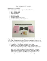
Tinker Tie Beta Assembly Instructions
● DIY Tinker Tie Kit starts here:
1. Open the box and inspect the components. There should be:
a. 28x RGB LEDs (SMD)
b. 12x Capacitors (SMD)
c. 1x Resistor (SMD)
d. 1x Tinker Tie PCB
e. 1x 500 mAh Battery
f. 1x Adafruit Pro Trinket (Optional)
g. 1x Adafruit Charging Backpack (Optional)
2. Begin by SMD (surface mount) soldering one side of the Tinker Tie at a time. If
using solder paste, it is ideal to apply solder paste to all contacts on one side of
the Tinker Tie, then place all components starting with the smaller capacitors and
resistors, then placing the larger LEDs.
a. The direction of the capacitors and resistor do not matter
b. When placing the LEDs, it is important to follow a pattern for their
direction. Each LED has a notch cut out of it. Each LED in a column needs
to have their notch pointing in the same direction. Look at the illustration
below for the pattern. The rightmost column has it’s LED notches all
facing the bottom right side, the next row to the left has all it’s notches
facing the top left. Alternate this pattern every column to the end. It is
extremely crucial to do this, as it won’t work any other way.


