Aria-24
ipe
Digital Key Telephone System
Installation Manual
Issue 1.5
Aria Technologies
31
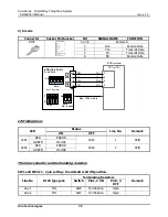
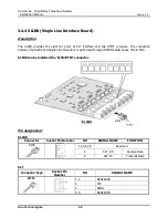
2) S mode
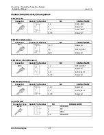
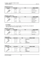
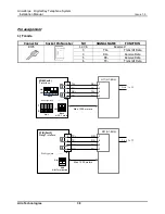
Connector
Pin Number
NO
SIGNAL NAME
FUNCTION
RJ45
1,2,7,8
Reserved
3
RX+
Receive Data
4
TX+
Transmit Data
5
TX-
Transmit Data
6
RX-
Receive Data
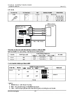
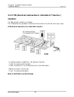
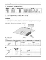
The line connector and terminating resistors of Basic BRI
SW5 and SW7
’s 1,2 pin setting : the default is all ON position
Line No
RJ45 type jack
Terminating Resistors
Remark
Switch
Pin1, 2 ON
Pin3, 4 OFF
Line 1
MJ1
SW5
Termination
Open
Line 2
MJ1
SW7
Termination
Open
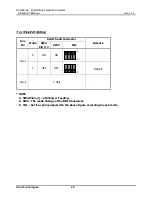
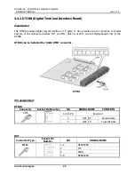
T or S Switch Setting of Basic BRI
Line No. Mode
Switch and Connector
Remark
SW5 Pin 3 4
SW7
CN21
Line 1
S
ON
ON
T
S
T
OFF
OFF
T
S
Default
T Only
* NOTE
1. SW5(Pin3, 4) : -40V Power Feeding.
2. SW7 : The mode Change of the BRI transceiver.
3. CN21 : Set four 2pin jumpers like the above figure according to each mode.
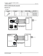
TE1(or TA)
3
6
4
5
TX+
TX
-
RX+
RX
-
BRI Port1 Only
RX+
RX
-
TX+
TX
-
3
6
4
S
interface
R
R
ISDN terminal
SW7
1
2
ON
ON : S mode
SW5
1
2
3
4
ON
T
S
CN2
1
5
RJ45 type jack
Max. 1000 meters

