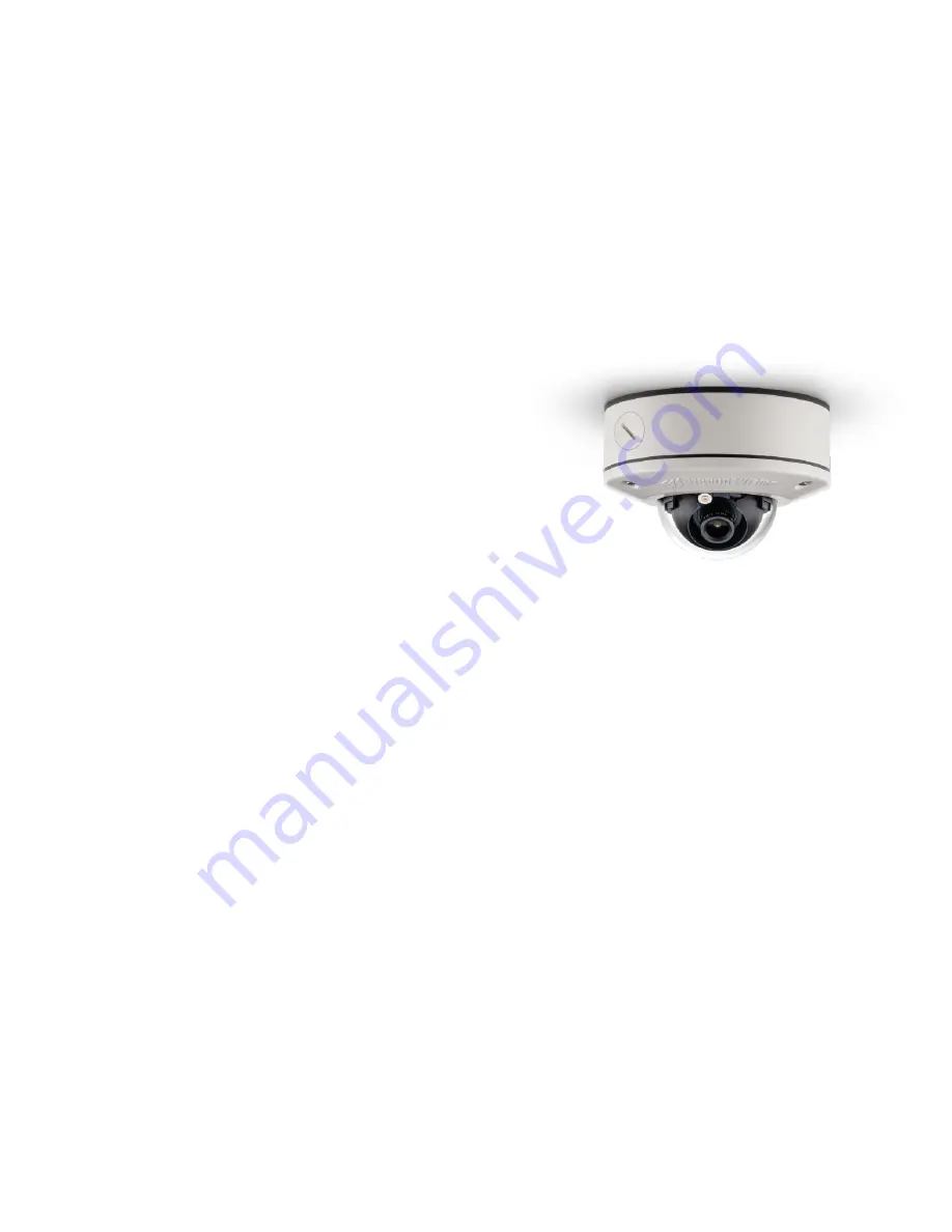
Arecont Vision MicroDome G2 AV1555DN-S Скачать руководство пользователя страница 1


Micro

Dome®   G2


-S Model Installation Manual


Models: 

1.2 Megapixel  

  AV1555DN-S 

  AV1555DN-S-NL  


1080p 

  AV2555DN-S 

  AV2556DN-S 

  AV2555DN-S-NL 

  AV2556DN-S-NL 


3 Megapixel 

  AV3555DN-S 

  AV3556DN-S 

  AV3555DN-S-NL 

  AV3556DN-S-NL 


5 Megapixel 

  AV5555DN-S 

  AV555DN-S-NL 

Содержание MicroDome G2 AV1555DN-S

Страница 1: ...l Installation Manual Models 1 2 Megapixel AV1555DN S AV1555DN S NL 1080p AV2555DN S AV2556DN S AV2555DN S NL AV2556DN S NL 3 Megapixel AV3555DN S AV3556DN S AV3555DN S NL AV3556DN S NL 5 Megapixel AV5555DN S AV555DN S NL ...

Страница 2: ... the Lens 12 Optional Removing the Bubble 13 Optional Connecting Digital I O 14 Camera Discovery Setup and Configuration 18 Network Protocols 18 General Remote Focus 19 Refined Remote Focus 20 AV IP Utility Focus Tab 22 Wall Mount Accessory MCD WMT 23 Pendant Mount Accessory MCD CMT 24 Mounting Template MicroDome G2 Camera 25 Mount Template MicroDome MCD WMT Wall Mount 26 Mount Template MicroDome ...

Страница 3: ...ich are compatible with mounting surface and of sufficient length and construction to insure a secure mount Package Contents This equipment should be unpacked and handled with care The original packaging is the safest container in which to transport the unit and can be used if returning the unit for service The packaging contains One 1 Arecont Vision MicroDome G2 Camera One 1 ceiling template One ...

Страница 4: ...cted to unusual stress neglect misuse abuse improper storage testing or connection or unauthorized repair or iv is no longer covered under the Warranty Period ARECONT VISION MAKE NO WARRANTIES OR CONDITIONS EXPRESS IMPLIED STATUTORY OR OTHERWISE OTHER THAN THE EXPRESS LIMITED WARRANTIES MADE BY ARECONT VISION ABOVE AND ARECONT VISION HEREBY SPECIFICALLY DISCLAIMS ALL OTHER EXPRESS STATUTORY AND IM...

Страница 5: ...ng 2 8mm 4mm 6mm 8mm 12mm and 16mm options The 3 axis adjustment cameras are available in 1 2MP 1080p 3MP and 5MP versions and are available in both recessed and surface mount configurations The S model cameras are ideal for indoor or outdoor use and deliver excellent low light imaging Cast aluminum housings combined with the polycarbonate bubble are vandal resistant IK 10 The S model MicroDome G2...

Страница 6: ... the three lens lock screws using the supplied flat head screwdriver Do not over torque the screws Figure 2 Optional further tighten three lens lock screws 4 The camera can be mounted two ways surface mount or via a junction box to a wall or ceiling Choose the best method for your installation below a Surface Mount use the supplied template to mark three desired holes there are six holes to choose...

Страница 7: ... supplied with the camera to create the best seal possible between the camera and the mounting surface and using the supplied gasket or b Junction Box install a 4 in gang box or square metal junction box not supplied Figure 4 NOTE ensure openings for cables are accounted for prior to installation Figure 4 Install 4S junction box not supplied c Insert the supplied gasket inside the gang box d Inser...

Страница 8: ... of view Then lock the camera head in place by tightening at least two of the three set screws with the supplied flat head screwdriver Figure 5 Do not over torque the screws Figure 5 Lock camera head after adjusting the field of view NOTE Ensure not to press the remote focus motor against the sides of the camera module when adjusting the field of view Figure 5 Figure 5 Remote focus motor 8 Install...

Страница 9: ...the two captive fasteners with the supplied Philips head screwdriver to secure the dome cover to the user supplied 4S junction box Tightly insert the two black plugs supplied with the MCD 4S for the remaining open holes Cut any excess off the rubber plugs flush against the dome cover with a utility knife Figure 7 Attach the MCD 4S accessory plate to the user supplied 4S junction box NOTE The suppl...

Страница 10: ...upport arecontvision com 1 818 937 0700 877 CAMERA 8 www arecontvision com avsales arecontvision com MicroDome G2 Figure 8 Surface mount configuration Reference Description 1 Ceiling 2 Gasket 3 NPT Port 4 Camera Housing 5 Dome Cover ...

Страница 11: ...tion Reference Description 1 Ceiling 2 4S Junction Box user supplied 3 Gasket 4 Camera Housing 5 MCD 4S Dome Cover Accessory fits common 4S junction box 10 Use the Arecont Vision software AV IP Utility located on the CD or available for download at our website www arecontvision com for camera discovery and setup see Instruction Manual located on the CD or available on our website ...

Страница 12: ...iver Reference Description 1 Captive Fasteners 2 Loosen the lens lock screws 3 using the supplied flat head screwdriver if necessary Only do so if the lens seems very tight when turning 3 Manually unscrew the lens counter clockwise this may take several seconds 4 Screw the replacement lens clockwise until you feel some resistance and hit a hard stop 5 Retighten the lens lock screws 3 if necessary ...

Страница 13: ...ity in an indoor environment the bubble can be easily removed 1 For a surface S model camera remove the dome cover by unscrewing the three captive fasteners Set the camera aside 2 Remove the three screws on the dome cover and remove metal plate 3 Remove the bubble and either discard or set aside for future use 4 Re fasten the metal plate with the three screws to the dome cover 5 Reinstall the dome...

Страница 14: ... See Table 1 for electrical characteristics Electrical Characteristics MIN MAX Input Voltage V Measured between and terminals ON 2 9 6 3 OFF 0 1 3 Output Current mA Measured between and terminals Applied Voltage Range 0 80V ON 50 OFF 0 1 Table 1 NOTE The digital input is electrically isolated from the rest of the camera s electrical circuitry via general purpose photo couplers The input is additio...

Страница 15: ...n com 1 818 937 0700 877 CAMERA 8 www arecontvision com avsales arecontvision com MicroDome G2 NOTE Table 2 shows the cable color for digital input and output Digital I O Orange Digital OUT Yellow Digital OUT White Digital IN Black Digital IN Table 2 ...

Страница 16: ...able local code 1 Connect the camera to a PoE port on 100Mbps network PoE switch using an Ethernet cable as shown in the image below Reference Description 1 PoE Connector CAUTION Make the connections inside a watertight compartment Isolate unused power wires individually After connections are made ensure that the watertight compartment is tightly closed and cables and conduits are properly sealed ...

Страница 17: ...as been established A green LED will blink when the camera has been accessed LED Status Description Yellow Flashing Link has been established Solid Normal Operation Green Flashing Camera has been accessed Normal operation Solid N A None None No Connection NOTE Wiring methods shall be in accordance with the National Electrical Code NFPA 70 ANSI and with all local codes and authorities having jurisd...

Страница 18: ... your camera or available on our website Network Protocols The Arecont Vision MegaVideo G5 cameras support RTSP RTP TCP RTP UDP HTTP DHCP TFTP QoS IP version 4 IPv4 and IP version 6 IPv6 RTSP Cameras communicate with video management systems over Real Time Streaming Protocol Do not change the RTSP port unless you are sure your VMS does not use the default setting RTP TCP The Real time Protocol Tra...

Страница 19: ...he IPv6 internet layer protocol for packet switched internetworking across multiple IP networks IPv6 uses 128 bit addresses which allows for many more devices and users on the internet as well as extra flexibility in allocating addresses and efficiency for routing traffic General Remote Focus 1 To control the remote focus via the web interface double click the camera within the AV IP Utility Figur...

Страница 20: ...ocus area turns to Green the autofocus is complete Refined Remote Focus 1 For a more refined detailed focus scroll to the Video Tab section and select the PTZ radial button 2 Choose an area that has a lot of objects or an area you have an interest in seeing more details Left click and drag the box to the area where you want to see finer details The image zooms in 3 Repeat until you are able to see...

Страница 21: ...ton 7 The camera proceeds to go through the short range adjustment around the original focus It stops at the best point of focus using the new reference area When the box around the image illuminates green the camera has completed the focus For an additional focus press the manual focus buttons 20 5 1 20 5 1 8 When satisfied with the camera s focus setting click the Video menu 9 Click the PTZ radi...

Страница 22: ...s Best for scenes that are completely out of focus The camera automatically scans the full focus range of the scene to find the best focus position Short range Focus Best for scenes that are slightly of out of focus The camera quickly fine tunes for a precise focus position Stop Stops any command in progress Focus Aid The higher the focus aid value means the more the lens is required to focus If t...

Страница 23: ...ews are 10x1 wood or sheet metal screws 4x mount anchors also included 2 Always ensure gaskets are properly seated 3 Use Teflon tape on threaded interfaces 4 3 8 male to 1 2 female NPT adapter included 5 Mount holes from camera housing to flange are not symmetrical Alignment features indicated must be properly lined up for mount hole alignment Alignment features must be aligned for proper installa...

Страница 24: ...for proper installation Installation Notes 1 3x mounting screws are 10x1 wood or sheet metal screws 3x mount anchors also included 2 Always ensure gaskets are properly seated 3 Use Teflon tape on threaded interfaces 4 3 8 male to 1 2 female NPT adapter included 5 Mount holes from camera housing to flange are not symmetrical Alignment features indicated must be properly lined up for mount hole alig...

Страница 25: ... Installation Manual Page 25 support arecontvision com 1 818 937 0700 877 CAMERA 8 www arecontvision com avsales arecontvision com MicroDome G2 Mounting Template MicroDome G2 Camera ...

Страница 26: ... Installation Manual Page 26 support arecontvision com 1 818 937 0700 877 CAMERA 8 www arecontvision com avsales arecontvision com MicroDome G2 Mount Template MicroDome MCD WMT Wall Mount ...

Страница 27: ... Installation Manual Page 27 support arecontvision com 1 818 937 0700 877 CAMERA 8 www arecontvision com avsales arecontvision com MicroDome G2 Mount Template MicroDome MCD CMT Pendant Mount ...

Страница 28: ... to factory default with AV200 or the camera webpage Upgrade to the latest firmware by visiting ArecontVision com Isolate the camera on a dedicated network and test with AV200 Swap the troubled camera with a known good camera to see if the problem follows the camera or stays at the location 3 Contact Arecont Vision Technical Support one of three ways 1 Online Portal Support ArecontVision com 2 Pho...

Отзывы: