126
XM-281
Removing
1. Loosen the clamp securing the fuel supply hose to
the fuel rail; then remove the hose from the fuel rail.
2. Disconnect the wiring harness from each injector.
3. Remove the screws securing the injector hold-down
plate to the throttle body assembly; then remove the
plate from the injectors.
4. Remove the fuel injectors from the throttle
body/intake manifold assembly.
Installing
1. Apply a light coat of oil to all O-rings; then install
the upper and lower O-rings onto each injector.
2. Install the injectors into the throttle body assembly.
3. Place the injector hold-down plate into position on
top of the injectors and secure with two screws.
4. Connect the fuel delivery hose to the fuel rail and
secure with a clamp.
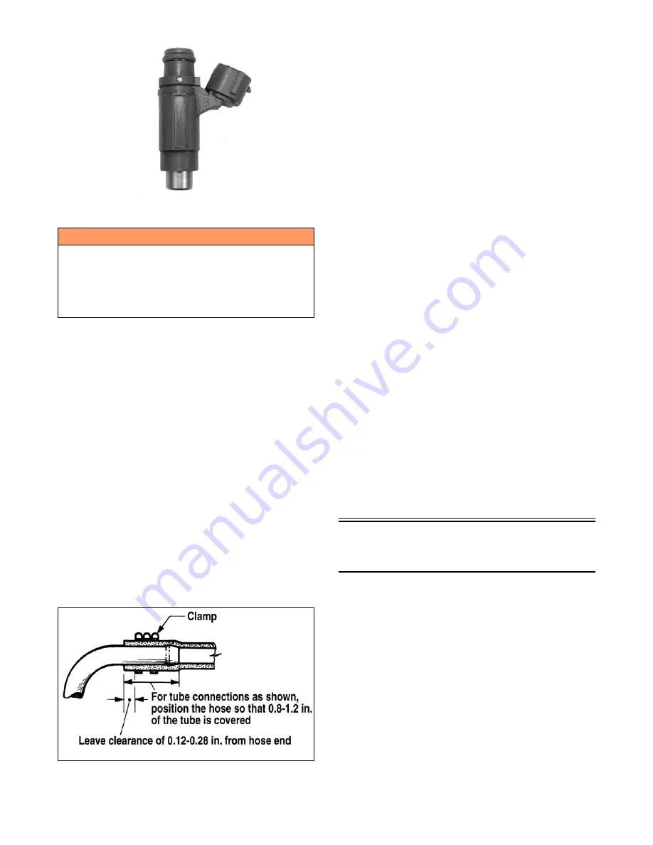
NOTE: When securing the fuel delivery hose, posi-
tion the clamp as shown.
729-325A
5. Connect the wiring harness to the injectors.
FUEL PRESSURE REGULATOR
The fuel pressure regulator maintains the fuel pressure at
a constant specified level.
EXHAUST TEMPERATURE SENSOR
This platinum, thin-film sensor detects the exhaust air
temperature in the exhaust system. The ECM sends cur-
rent to this sensor, and (depending on the temperature)
the sensor will pass a portion of that current to ground.
The ECM measures how much current passes through the
sensor to ground. From this measurement, the ECM
determines the exhaust air temperature and adjusts the
fuel, ignition timing, and APV calibration. Resistance
will increase as the temperature rises.
FUEL PUMP CIRCUIT
The fuel pump and its circuit are provided with current
from the fuel pump coil on the stator. For this circuit to
function correctly, five components must be properly
functioning. Check the following components before
considering the fuel pump assembly to be defective.
A. Fuel pump coil - see coil test procedure.
B. Emergency stop switch and ignition switch must be
ON.
C. Fuel pump - see fuel pump test procedure.
D. Wiring harness and connectors - clean the connectors
and test the harness.
E. ECM.
KNOCK SENSOR
This sensor controls engine knock or detonation. The
knock sensor assesses structure borne noise (vibrations)
caused by rapid pressure rises (detonation) in either cyl-
inder and performs calibration adjustments to the neces-
sary cylinder via the ECM limiting damage to internal
engine components. Detonation can be caused by many
variables including poor fuel quality, lean operating con-
ditions, or modified engine components/systems.
Self-Diagnostic
System/Codes (4000)
INTRODUCTION
The Diagnostic Code Alarm is controlled by the ECM. If
a code illuminates while the engine is running, the ECM
is receiving input that is outside of its established param-
eters.
WARNING
Since the fuel supply hose may be under pressure,
remove it slowly to release the pressure. Place an absor-
bent towel around the connection to absorb gasoline;
then remove the hose slowly to release the pressure.
Always wear safety glasses when removing the fuel
hoses.
Содержание M 8000
Страница 1: ...www arcticcat com SERVICE MANUAL www arcticcat com...
Страница 42: ...41 500cc_2A_15...
Страница 50: ...49 600_14_2...
Страница 58: ...57 800_12_2...
Страница 155: ...154 Troubleshooting Servomotor SERVO1A16...
Страница 156: ...155 SERVO2rv16...
Страница 193: ...192 0747 414 M 141 High Country Models...
Страница 209: ...208 NOTES...
Страница 210: ...Printed in U S A Trademarks of Arctic Cat Inc Thief River Falls MN 56701 p n 2260 847...


