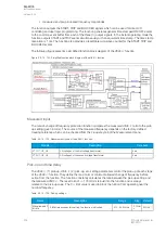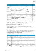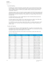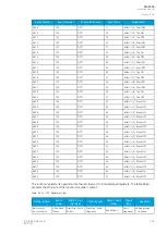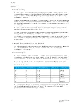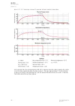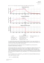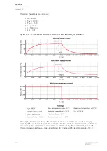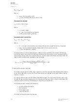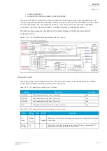
Table. 5.3.18 - 153. Event codes.
Event number
Event channel
Event block name
Event code
Description
6528
102
RPW1
0
Start ON
6529
102
RPW1
1
Start OFF
6530
102
RPW1
2
Trip ON
6531
102
RPW1
3
Trip OFF
6532
102
RPW1
4
Block ON
6533
102
RPW1
5
Block OFF
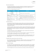
The function registers its operation into the last twelve (12) time-stamped registers. The register of the
function records the ON event process data for START, TRIP or BLOCKED. The table below
presents the structure of the function's register content.
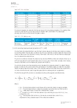
Table. 5.3.18 - 154. Register content.
Date and time
Event code
Pre-trigger
power
Fault
power
Pre-fault
power
Trip time
remaining
Used SG
dd.mm.yyyy
hh:mm:ss.mss
6528-6533
Descr.
Start/Trip -20ms
power
Start/Trip
power
Start -200ms
power
0 ms...1800s
Setting group
1...8 active
5.3.19 Line thermal overload protection (TF>; 49F)
The line thermal overload function is used for the thermal capacity monitoring and protection of cables
and overhead lines. This function can also be used for any single time constant application like inductor
chokes, certain types of transformers and any other static units which do not have active cooling apart
from the cables and overhead lines.
The function constantly monitors the instant values of phase TRMS currents (including harmonics up to
31
st
) and calculates the set thermal replica status in 5 ms cycles. The function includes a total memory
function of the load current conditions according to IEC 60255-8.
The function is based on a thermal replica which represents the protected object's or cable's thermal
loading in relation to the current going through the object. The thermal replica includes the calculated
thermal capacity that the "memory" uses; it is an integral function which tells this function apart from a
normal overcurrent function and its operating principle for overload protection applications.
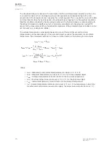
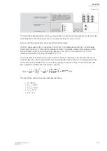
The thermal image for the function is calculated according to the equation described below:
Where:
• θ
t%
= Thermal image status in percentages of the maximum thermal capacity available
• θ
t-1
= Thermal image status in a previous calculation cycle (the memory of the function)
• I
max
= Measured maximum of the three TRMS phase currents
• I
n
= Current for the 100 % thermal capacity to be used (the pick-up current in p.u., t
max
achieved in τ x 5)
• k
SF
= Loading factor (service factor), the maximum allowed load current in p.u.,
dependent on the protected object or the cable/line installation
A
AQ
Q-F205
-F205
Instruction manual
Version: 2.04
216
© Arcteq Relays Ltd
IM00013
Содержание AQ F205
Страница 1: ...AQ F205 Feeder protection IED Instruction manual ...
Страница 2: ......
Страница 379: ...Figure 7 4 245 Example block scheme A AQ Q F205 F205 Instruction manual Version 2 04 Arcteq Relays Ltd IM00013 377 ...
Страница 389: ...Figure 8 7 254 Device installation A AQ Q F205 F205 Instruction manual Version 2 04 Arcteq Relays Ltd IM00013 387 ...

