92
Technical Specifications and Operating Parameters
Model 1093A/B/C:
430-mm W x 44-mm H x 280-mm D (16.9-in. x 1.7-in. x 11.0-in.)
Model 1092A/B/C:
218-mm W x 44-mm H x 260-mm D (8.6-in. x 1.7-in. x 10.5-in)
Antenna:
77-mm diameter x 66-mm height (3.05-in. x 2.61-in.)
Table A.2: Clock and Antenna Dimensions
Model 1092A/B/C
Model 1093A/B/C
1.4 kg (3.0 lbs.) net. (Instrument)
1.9 kg (4.3 lbs.) net. (Instrument)
2.0 kg (4.4 lbs.) net. (Antenna and Cable)
2.0 kg (4.4 lbs.) net. (Antenna and Cable)
4.5 kg (10 lbs.) includes antenna, cables and ac-
cessories (Shipping)
5.5 kg (12 lbs.) includes antenna, cables, and
accessories. (Shipping)
Table A.3: Clock and Shipping Weights
A.7
Physical Specifications
A.7.1
Dimensions
A.7.2
Weight
A.8
Temperature and Humidity
A.9
Power Requirements
Model 1092A/B/C
The Model 1092A/B/C comes standard with an external 120 VAC to 9 VDC
wall-mount transformer that connects to the rear panel. It will also operate from a battery source
from 8 to 15 VDC at 500-mA. Additionally, the antenna receives power through the antenna cable
connected to the Type F antenna connector on the rear panel of the Model 1092A/B/C.
Model 1093A/B/C
The Model 1093A/B/C comes with one of three user-specified internal power
supplies. Additionally, the antenna receives power through the antenna cable connected to the Type
F connector on the rear panel of the Model 1093A/B/C.
•
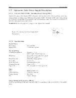
Option 07: 85 - 264 VAC, 47 - 440 Hz, or 110 - 350 VDC,
<
20 W typical (Standard power
supply).
•
Option 08: 10 - 60 VDC (DC only),
<
20 W typical. Uses a three-position terminal strip in
place of the IEC-320 power inlet module; includes Surge-Withstand Capability.
•
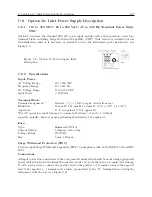
Option 10: 110 - 350 VDC,
<
20 VA or 85 - 264 VAC, 47 - 440 Hz, with three-position
Terminal Power Strip and Surge-Withstand Capability.
A.9.1
Power Connector (Model 1093A/B/C)
•
Option 7, Standard Power Supply: This includes a fused IEC-320 power inlet module with
mating ac cord. Plug type specified as Options P1 through P10 (see Section 3.1.1).
•
Options 08 and 10: Using a 3-pole terminal strip power inlet with Surge-Withstand Capability
(see Section 3.2 and 3.3).
Содержание 1092A
Страница 4: ...iv ...
Страница 18: ...xviii LIST OF TABLES ...
Страница 129: ...C 10 Option 20A Four Fiber Optic Outputs 111 Figure C 7 Option 20A Jumper Locations ...
Страница 131: ...C 11 Option 27 8 Channel High Drive 113 Figure C 8 Option 27 Jumper Locations ...
Страница 148: ...130 Options List Figure C 10 Option 29 Connector Signal Locations ...

