3.8 Connecting Output Signals
17
3.7.1
Replacing Fuses
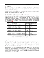
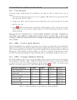
An IEC-320 power inlet connector includes a 1-A, 250-V fast acting fuse. The fuse is contained in
a small compartment with a snap-fit latch, which also has a compartment for a spare fuse. The
fuse compartment is located directly adjacent to the input connector socket, and can be opened by
pulling both sides directly out away from the chassis, or by gently prying with a small flag-blade
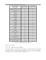
screwdriver. Check Table 3.2 for replacement fuse information.
To replace the fuse, first disconnect the line cord from the power source and then remove the cord
from the rear-panel IEC connector. The in-circuit fuse is the innermost one; inspect it to deterrmine
if it is open. As required, replace with fuse in the outer compartment, and replace the spent fuse.
With an Option 07, 08 or 15A/15B, the input power module includes separate fuse holder adjacent
to the terminal power strip. To check the fuse, first disconnect power to the clock. Grasp the
fuse-holder cover and turn it counter-clockwise. The cover and fuse should pop out. CAUTION:
Replace fuse only with another of the same type and rating. See Table 3.2 above for the correct
fuse configured for your option.
3.8
Connecting Output Signals
Output signals may be connected through designated standard BNC or option connector. For
standard I/O connectors, see Section 2.3.6. Connectors are standard female BNC. For Options
that have terminals for output connectors, see Appendix C for details about those options and
connectors. As an example, the Option 27 uses Phoenix-style terminals with 5-mm spacing and
will accept between 0.25 and 2.5–mm wire diameter. BNC connectors (on installed option boards)
are female and require only connecting the (male) connector into it. For technical details concerning
the various timing signals, see Chapter 7.
3.9
Connecting Input Signals
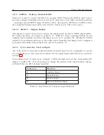
Input signals may be connected through the designated I/O terminals, J2, J3, J4, and J5. J2 is used
for auxiliary inputs, J3 and J4 are both used for timing events and J5 can be used to connect an
external timing reference, instead of using the internal oscillator. For standard I/O connectors, see
Section 2.3.6. BNC connectors (on installed option boards) are female and require only connecting
the (male) connector into it.
3.9.1
Connecting an Event Input at J3 or J4
An event input may be connected to the Model 1088B series clock through two I/O connectors: J3
(Event B) and J4 (Event A). Refer to the rear-panel drawing in Figure 2.2.
Содержание 1088A
Страница 4: ...iv ...
Страница 6: ...vi ...
Страница 18: ...xviii LIST OF FIGURES ...
Страница 23: ...1 4 Attaching Rack Mount Ears to 1088A B Series Clocks 3 Figure 1 2 Attaching Rack Mount Ears ...
Страница 24: ...4 Unpacking the Clock ...
Страница 32: ...12 Front and Rear Panels ...
Страница 38: ...18 Connecting Inlet Power Input and Output Signals ...
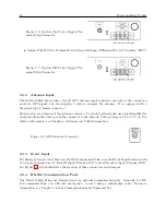
Страница 41: ...4 1 GPS Antenna Installation 21 Figure 4 2 Antenna Mounting Bracket Figure 4 3 Antenna Mounting with AS0044600 ...
Страница 46: ...26 GPS Antenna and Cable Information ...
Страница 48: ...28 Setting Internal Jumpers Figure 5 1 Model 1088B Main Board ...
Страница 76: ...56 The Setup Menus ...
Страница 112: ...92 Serial Communication and Command Set ...
Страница 127: ...B 4 Physical Dimensions 107 Figure B 1 Suggested Mounting of the AS0094500 Surge Arrester ...
Страница 128: ...108 Using Surge Arresters ...
Страница 137: ...C 5 Option 04 Parallel BCD Output 117 C 5 2 Option 04 Firmware Setup Figure C 2 Option 04 Firmware Setup ...
Страница 145: ...C 5 Option 04 Parallel BCD Output 125 Figure C 4 Option 04 Output Jumper Settings ...
Страница 146: ...126 Options List Figure C 5 Option 04 Board Layout and Jumper Locations ...
Страница 165: ...C 12 Option 17 Parallel BCD Output and Second RS 232 Port 145 Figure C 11 Option 17 Output Jumper Settings ...
Страница 166: ...146 Options List Figure C 12 Option 17 Board Layout and Jumper Locations ...
Страница 176: ...156 Options List C 14 5 Typical Network Configuration Figure C 15 Option 18 Network Configuration ...
Страница 187: ...C 16 Option 20A Four Fiber Optic Outputs 167 Figure C 22 Option 20A Jumper Locations ...
Страница 194: ...174 Options List Figure C 24 Option 23 Internal Jumper Setup ...
Страница 196: ...176 Options List Figure C 25 Option 27 Jumper Locations ...
Страница 214: ...194 Options List Figure C 28 Option 29 Connector Signal Locations ...
Страница 270: ...250 Options List ...


