118
Options List
C.5.3
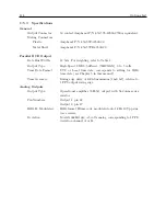
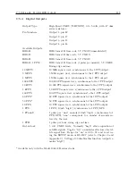
Specifications
General
Output Connector:
50 contact;Amphenol P/N 850-57L-40500-2700or equivalent.
Mating Connectors:
Plastic:
Amphenol P/N 850-57F-30500-20
Metal Shell:
Amphenol P/N 850-57FE-30500-20
Parallel BCD Output
Data Bus Width:
42 bits. For weighting, refer to Table 1.
Output Type:
High-Speed CMOS, buffered, (74HCXXX), 0 to 5 volts.
Time Data Format:
UTC or Local time data; corresponds to setting for IRIG
time data (see Chapter 5 in this manual).
Time Accuracy:
Rising edge delay of 100 nS maximum (1 mS bit), relative to
1 PPS output rising edge.
Analog Outputs
Output Type:
Operational amplifier (LF353) output, with 562 ohm series
resistor.
Pin Numbers:
Output 1: pin 22
Output 2: pin 47
IRIG-B, Modulated:
IRIG format B time code, modulated onto 1 kHz 10 Vpp sine
wave carrier.
Deviation:
Model 1088B Only;
±
5 volts analog, corresponding to 1 PPS
deviation channel A or B.
Содержание 1088A
Страница 4: ...iv ...
Страница 6: ...vi ...
Страница 18: ...xviii LIST OF FIGURES ...
Страница 23: ...1 4 Attaching Rack Mount Ears to 1088A B Series Clocks 3 Figure 1 2 Attaching Rack Mount Ears ...
Страница 24: ...4 Unpacking the Clock ...
Страница 32: ...12 Front and Rear Panels ...
Страница 38: ...18 Connecting Inlet Power Input and Output Signals ...
Страница 41: ...4 1 GPS Antenna Installation 21 Figure 4 2 Antenna Mounting Bracket Figure 4 3 Antenna Mounting with AS0044600 ...
Страница 46: ...26 GPS Antenna and Cable Information ...
Страница 48: ...28 Setting Internal Jumpers Figure 5 1 Model 1088B Main Board ...
Страница 76: ...56 The Setup Menus ...
Страница 112: ...92 Serial Communication and Command Set ...
Страница 127: ...B 4 Physical Dimensions 107 Figure B 1 Suggested Mounting of the AS0094500 Surge Arrester ...
Страница 128: ...108 Using Surge Arresters ...
Страница 137: ...C 5 Option 04 Parallel BCD Output 117 C 5 2 Option 04 Firmware Setup Figure C 2 Option 04 Firmware Setup ...
Страница 145: ...C 5 Option 04 Parallel BCD Output 125 Figure C 4 Option 04 Output Jumper Settings ...
Страница 146: ...126 Options List Figure C 5 Option 04 Board Layout and Jumper Locations ...
Страница 165: ...C 12 Option 17 Parallel BCD Output and Second RS 232 Port 145 Figure C 11 Option 17 Output Jumper Settings ...
Страница 166: ...146 Options List Figure C 12 Option 17 Board Layout and Jumper Locations ...
Страница 176: ...156 Options List C 14 5 Typical Network Configuration Figure C 15 Option 18 Network Configuration ...
Страница 187: ...C 16 Option 20A Four Fiber Optic Outputs 167 Figure C 22 Option 20A Jumper Locations ...
Страница 194: ...174 Options List Figure C 24 Option 23 Internal Jumper Setup ...
Страница 196: ...176 Options List Figure C 25 Option 27 Jumper Locations ...
Страница 214: ...194 Options List Figure C 28 Option 29 Connector Signal Locations ...
Страница 270: ...250 Options List ...


