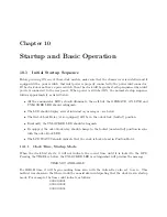
Chapter 10
Startup and Basic Operation
10.1
Initial Startup Sequence
Before powering ON any of these clock models, make sure that the chassis cover is installed and if
equipped with a power switch, that inlet power is properly connected to the power inlet connector.
If the clock does not have a power switch, then the clock will begin the startup sequence when inlet
power is connected to the rear panel. When power is switched ON, the normal startup sequence
follows approximately as listed below:
•
All the annunciator LED’s should illuminate, then all but the OPERATE, ON LINE and
UNLOCKED LED should extinguish.
•
The LCD should display several introductory messages – see below.
•
The Out-of-Lock Relay (if so equipped) will be in the out-of-lock (faulted) position.
•
Eventually, the UNLOCKED LED should extinguish.
•
If equipped, the out-of-lock relay should change to the locked (non-faulted) position in sync
with the out-of-lock LED.
•
The LCD STATUS should indicate that the clock is Locked and in Position Hold.
10.1.1
Clock Time, Startup Mode
When the clock first starts, it will not indicate the correct time until it is locked to the GPS.
Pressing the TIME key before the UNLOCKED LED is extinguished will produce the message:
TIME NOT AVAILABLE
For IRIG-B time, it will begin counting from zero, with the Julian Day also set to zero. This
method was chosen so that there would be no mistake in interpreting that the clock was in startup
mode. For example, the time could indicate as follows:
000:00:00:01
000:00:00:02
000:00:00:03
.
Содержание 1088A
Страница 4: ...iv ...
Страница 6: ...vi ...
Страница 18: ...xviii LIST OF FIGURES ...
Страница 23: ...1 4 Attaching Rack Mount Ears to 1088A B Series Clocks 3 Figure 1 2 Attaching Rack Mount Ears ...
Страница 24: ...4 Unpacking the Clock ...
Страница 32: ...12 Front and Rear Panels ...
Страница 38: ...18 Connecting Inlet Power Input and Output Signals ...
Страница 41: ...4 1 GPS Antenna Installation 21 Figure 4 2 Antenna Mounting Bracket Figure 4 3 Antenna Mounting with AS0044600 ...
Страница 46: ...26 GPS Antenna and Cable Information ...
Страница 48: ...28 Setting Internal Jumpers Figure 5 1 Model 1088B Main Board ...
Страница 76: ...56 The Setup Menus ...
Страница 112: ...92 Serial Communication and Command Set ...
Страница 127: ...B 4 Physical Dimensions 107 Figure B 1 Suggested Mounting of the AS0094500 Surge Arrester ...
Страница 128: ...108 Using Surge Arresters ...
Страница 137: ...C 5 Option 04 Parallel BCD Output 117 C 5 2 Option 04 Firmware Setup Figure C 2 Option 04 Firmware Setup ...
Страница 145: ...C 5 Option 04 Parallel BCD Output 125 Figure C 4 Option 04 Output Jumper Settings ...
Страница 146: ...126 Options List Figure C 5 Option 04 Board Layout and Jumper Locations ...
Страница 165: ...C 12 Option 17 Parallel BCD Output and Second RS 232 Port 145 Figure C 11 Option 17 Output Jumper Settings ...
Страница 166: ...146 Options List Figure C 12 Option 17 Board Layout and Jumper Locations ...
Страница 176: ...156 Options List C 14 5 Typical Network Configuration Figure C 15 Option 18 Network Configuration ...
Страница 187: ...C 16 Option 20A Four Fiber Optic Outputs 167 Figure C 22 Option 20A Jumper Locations ...
Страница 194: ...174 Options List Figure C 24 Option 23 Internal Jumper Setup ...
Страница 196: ...176 Options List Figure C 25 Option 27 Jumper Locations ...
Страница 214: ...194 Options List Figure C 28 Option 29 Connector Signal Locations ...
Страница 270: ...250 Options List ...

