86
Serial Communication and Command Set
9.2.9
Date and Time Commands
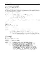
Set Receiver Time
Command:
yyyy:mm:dd:hh:mmTS
TS sets the receiver time to the entered value (UTC format),
only when not locked to the GPS
. The
command is ignored when locked to satellites. When the receiver is initially activated, and has not
locked onto satellites, acquisition time may be improved by giving the clock an initial estimate of
UTC time, which it can use (with stored position and almanac data) to determine which satellites
and Doppler shifts to use in acquisition.
Response:
C
Format:
yyyy = year
mm = month
dd
= day
hh
= hour
mm = minute
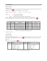
Return Local Date
Command:
DL
DL returns the current date, in the Local time zone.
Response:
ddmmmyyyy
C
Return UTC Date
Command:
DU
DU returns the current date, in the UTC time zone.
Response:
ddmmmyyyy
C
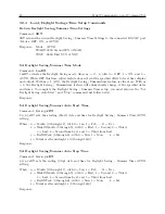
Return Local Time
Command:
TL
TL returns the current Local time.
Response:
ddd:hh:mm:ss
C
Return UTC Time
Command:
TU
TU returns current UTC time.
Response:
ddd:hh:mm:ss
C
Содержание 1088A
Страница 4: ...iv ...
Страница 6: ...vi ...
Страница 18: ...xviii LIST OF FIGURES ...
Страница 23: ...1 4 Attaching Rack Mount Ears to 1088A B Series Clocks 3 Figure 1 2 Attaching Rack Mount Ears ...
Страница 24: ...4 Unpacking the Clock ...
Страница 32: ...12 Front and Rear Panels ...
Страница 38: ...18 Connecting Inlet Power Input and Output Signals ...
Страница 41: ...4 1 GPS Antenna Installation 21 Figure 4 2 Antenna Mounting Bracket Figure 4 3 Antenna Mounting with AS0044600 ...
Страница 46: ...26 GPS Antenna and Cable Information ...
Страница 48: ...28 Setting Internal Jumpers Figure 5 1 Model 1088B Main Board ...
Страница 76: ...56 The Setup Menus ...
Страница 112: ...92 Serial Communication and Command Set ...
Страница 127: ...B 4 Physical Dimensions 107 Figure B 1 Suggested Mounting of the AS0094500 Surge Arrester ...
Страница 128: ...108 Using Surge Arresters ...
Страница 137: ...C 5 Option 04 Parallel BCD Output 117 C 5 2 Option 04 Firmware Setup Figure C 2 Option 04 Firmware Setup ...
Страница 145: ...C 5 Option 04 Parallel BCD Output 125 Figure C 4 Option 04 Output Jumper Settings ...
Страница 146: ...126 Options List Figure C 5 Option 04 Board Layout and Jumper Locations ...
Страница 165: ...C 12 Option 17 Parallel BCD Output and Second RS 232 Port 145 Figure C 11 Option 17 Output Jumper Settings ...
Страница 166: ...146 Options List Figure C 12 Option 17 Board Layout and Jumper Locations ...
Страница 176: ...156 Options List C 14 5 Typical Network Configuration Figure C 15 Option 18 Network Configuration ...
Страница 187: ...C 16 Option 20A Four Fiber Optic Outputs 167 Figure C 22 Option 20A Jumper Locations ...
Страница 194: ...174 Options List Figure C 24 Option 23 Internal Jumper Setup ...
Страница 196: ...176 Options List Figure C 25 Option 27 Jumper Locations ...
Страница 214: ...194 Options List Figure C 28 Option 29 Connector Signal Locations ...
Страница 270: ...250 Options List ...


