6.2 Setting the Main RS-232C Port
33
6.2.1
Setting Port Parameters
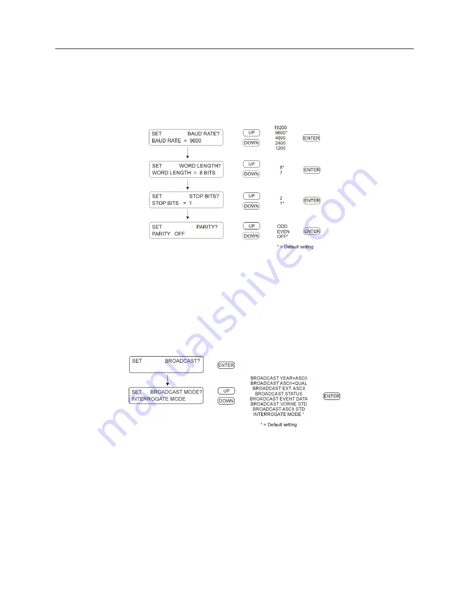
Enter this menu from the “Set Main RS-232?” menu; see Figure 6.1. The “Set Port Config” menu
allows you to configure any of the RS-232C port parameters from the front panel. Use the UP and
DOWN keys to adjust the parameter values.
RS-232C: Port parameters may not be changed from
RS-232C ports. They may only be changed with Models 1084B/C series clocks from the front panel
.
Figure 6.2: Port Parameter Setup
6.2.2
Setting the Broadcast Mode from Main RS-232
Enter this menu from the “Set Main RS-232?” menu; see Figure 6.1. The “Set Broadcast Mode”
menu allows you to configure the Model 1084A/B/C to broadcast ASCII time/date-related data
from the available RS-232C ports. With the UP/DOWN keys select the desired broadcast mode
and press ENTER to immediately start the broadcast.
RS-232C: see Section 9.2.1
Figure 6.3: Broadcast Setup
Содержание 1084A
Страница 4: ...iv ...
Страница 6: ...vi ...
Страница 18: ...xviii LIST OF FIGURES ...
Страница 23: ...1 4 Attaching Rack Mount Ears to 1084A B C Series Clocks 3 Figure 1 2 Attaching Rack Mount Ears ...
Страница 24: ...4 Unpacking the Clock ...
Страница 36: ...16 Connecting Inlet Power Input and Output Signals ...
Страница 39: ...4 1 GPS Antenna Installation 19 Figure 4 2 Antenna Mounting Bracket Figure 4 3 Antenna Mounting with AS0044600 ...
Страница 44: ...24 GPS Antenna and Cable Information ...
Страница 114: ...94 Startup and Basic Operation ...
Страница 123: ...B 4 Physical Dimensions 103 Figure B 1 Suggested Mounting of the AS0094500 Surge Arrester ...
Страница 124: ...104 Using Surge Arresters ...
Страница 134: ...114 Options List C 6 2 Option 06 Firmware Setup Figure C 3 Option 06 Firmware Setup ...
Страница 142: ...122 Options List Figure C 5 Option 06 Output Jumper Settings ...
Страница 143: ...C 6 Option 06 Parallel BCD Output 1 millisecond Resolution 123 Figure C 6 Option 06 Board Layout and Jumper Locations ...
Страница 157: ...C 10 Option 17 Parallel BCD Output and Second RS 232C Port 137 Figure C 12 Option 17 Output Jumper Settings ...
Страница 158: ...138 Options List Figure C 13 Option 17 Board Layout and Jumper Locations ...
Страница 163: ...C 13 Option 20A Four Fiber Optic Outputs 143 Figure C 14 Option 20A Jumper Locations ...
Страница 170: ...150 Options List Figure C 16 Option 23 Internal Jumper Setup ...
Страница 172: ...152 Options List Figure C 17 Option 27 Jumper Locations ...
Страница 190: ...170 Options List Figure C 20 Option 29 Connector Signal Locations ...
Страница 246: ...226 Options List ...


