2
- 41
OPERACIONES DE MANTENIMIENTO PERIÓDICO Y DE
PUESTA A PUNTO
PERIODIC SERVICE AND SETTING UP OPERATIONS
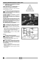
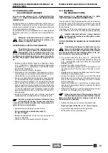
2.20 AJUSTE DEL PEDAL
DEL FRENO TRASERO
El pedal del freno está colocado ergonómicamente en
fase de ensamblaje del vehículo.
Si es necesario, se puede personalizar la posición, en al-
tura, del pedal del freno:
◆
Apoye el vehículo sobre el soporte.
◆
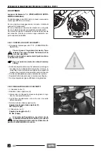
Afloje la contratuerca (1).
◆
Atornille del todo el tensor del freno (2).
◆
Atornille del todo la contratuerca (3) sobre la varilla
mando bomba (4).
◆
Atornille del todo la varilla mando bomba (4), luego
desenrósquela dándole 3 - 4 vueltas.
◆
Destornille el tensor del freno (2) hasta que el pedal
del freno alcance la altura deseada.
◆
Bloquee el tensor del freno (2) por medio de la contra-
tuerca (1).
◆
Desenrosque la varilla mando bomba (4) y llévela a
contacto con el pistón bomba.
◆
Enrosque la varilla para garantizar un juego mínimo de
0,5
÷
1 mm entre la varilla mando bomba (4) y el pis-
tón bomba.
Controle que haya juego entre el tensor del
freno (2) y el elemento de contacto, para evitar
que el freno quede accionado causando un
desgaste prematuro de los elementos de frenado.
Juego entre el tensor del freno y el elemento de con-
tacto: 0,5
÷
1 mm.
◆
Bloquee la varilla mando bomba por medio de la con-
tratuerca (3).
Después del ajuste, al soltar el freno controle
que la rueda gire libremente.
2.21 AJUSTE DE LA PALANCA DEL FRENO
DELANTERO
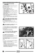
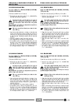
Si comprueba que la palanca (5) tiene juego, proceda de
la siguiente manera:
◆
Apoye el vehículo sobre el soporte.
◆
Elimine el juego mediante el tornillo (6).
El tornillo (6) debe tener contacto con el ele-
mento bombeador pero no debe presionar
más allá, de otra manera se tendrá un frenado
mínimo pero continuo.
2.22 COMPROBACION DESGASTE PASTILLAS
Controle el desgaste de las pastillas del freno después
de los primeros 1000 km; luego cada 6000 km.
El desgaste de las pastillas del freno de disco depende
del uso, del tipo de conducción y de la carretera.
El desgaste es mayor cuando se conduce en carreteras
polvorientas o mojadas.
Para realizar un control rápido del desgaste de las pasti-
llas hay que:
◆
Colocar el vehículo sobre el caballete, véase pág. 35
(COLOCACION DEL VEHICULO SOBRE EL CABA-
LLETE).
◆
Efectuar un control visual entre la pinza del freno y las
pastillas, actuando:
- desde abajo para la pinza del freno delantero (7).
- desde arriba para la pinza del freno trasero (8).
◆
Si el espesor del material de fricción (incluso de una
sola pastilla) queda reducido al valor aproximado de 1
mm, sustituya ambas pastillas, véase 7.5.1 y 7.6.1
(SUBSTITUCIÓN DE LAS PASTILLAS DE FRENO).
a
a
a
2.20 REAR BRAKE PEDAL
ADJUSTMENT
The brake pedal is positioned ergonomically during the
assembly of the vehicle.
If necessary, it is possible to adjust the height of the
brake pedal:
◆
Position vehicle on stand.
◆
Loosen the lock nut (1).
◆
Screw the brake adjuster (2) completely.
◆
Screw the lock nut (3) completely on the pump control
rod (4).
◆
Screw the pump control rod (4) completely, then un-
screw it by giving 3-4 turns.
◆
Unscrew the brake adjuster (2) until the brake pedal
reaches the desired height.
◆
Lock the brake adjuster (2) by means of the lock nut
(1).
◆
Unscrew the pump control rod (4) and bring it in con-
tact with the pump piston.
◆
Screw the rod in order to ensure a minimum clearance
of 0.5
÷
1 mm between the pump control rod (4) and the
pump piston.
Make sure that there is a certain clearance be-
tween the brake adjuster (2) and the point of
contact, to prevent the brake from remaining
operated and the consequent untimely wear of the
braking elements.
Clearance between brake adjuster and point of con-
tact: 0.5
÷
1 mm.
◆
Lock the pump control rod by means of the lock nut (3).
After the adjustment, make sure that the
wheel rotates freely with released brake.
2.21 FRONT BRAKE LEVER ADJUSTMENT
If play is observed in the movement of the lever (5) pro-
ceed as follows:
◆
Position the vehicle on stand.
◆
Adjust the screw (6), eliminating the play.
The screw should be in contact with the
pumping element but must not press beyond
it otherwise there will be a minimum but con-
tinuous braking.
2.22 CHECKING THE BRAKE PAD WEAR
Check the brake pad wear after the first 1000 km and
successively every 6000 km.
The wear of the brake pads depends on the use, on the
kind of drive and on the road.
The wear will be greater when the vehicle is driven on
dirty or wet roads.
To carry out a rapid checking of the wear of the pads, pro-
ceed as follows:
◆
Position the vehicle on the stand, see p. 35 (POSI-
TIONING THE VEHICLE ON THE STAND).
◆
Carry out a visual checking of the friction material
thickness by looking between the brake caliper and
the pads. Proceed:
- from below for the front brake caliper (7);
- from above for the rear brake caliper (8).
◆
If the thickness of the friction material (even of one pad
only) has reduced to about 1 mm, replace both pads,
see 7.5.1 and 7.6.1 (CHANGING THE BRAKE PADS).
a
a
a
Содержание Pegaso 650
Страница 1: ......
Страница 3: ...0 4 NOTE NOTES ANMERKUNGEN ...
Страница 4: ...1 1 1 2 3 4 5 6 7 8 INFORMAZIONI GENERALI INFORMACIONES GENERALES GENERAL INFORMATION ...
Страница 42: ......
Страница 69: ...3 1 1 2 3 4 5 6 7 8 MOTORE MOTOR ENGINE ...
Страница 90: ...3 22 MOTORE NOTE NOTAS NOTES ...
Страница 91: ...4 1 1 2 3 4 5 SISTEMA DI ALIMENTAZIONE SISTEMA DE ALIMENTACIÓN FUEL SYSTEM ...
Страница 116: ...4 26 SISTEMA DI ALIMENTAZIONE NOTE NOTAS NOTES ...
Страница 117: ...5 1 1 2 3 4 5 6 7 8 IMPIANTO DI RAFFREDDAMENTO SISTEMA DE REFRIGERACIÓN COOLING SYSTEM ...
Страница 130: ...5 14 IMPIANTO DI RAFFREDDAMENTO SISTEMA DE REFRIGERACIÓN COOLING SYSTEM NOTE NOTAS NOTES ...
Страница 131: ...6 1 6 1 2 3 4 5 6 7 8 IMPIANTO ELETTRICO INSTALACIÓN ELÉCTRICA ELECTRICAL SYSTEM ...
Страница 176: ...IMPIANTO ELETTRICO INSTALACIÓN ELÉCTRICA ELECTRICAL SYSTEM 6 46 NOTE NOTAS NOTES ...
Страница 177: ...7 1 1 2 3 4 5 6 7 8 CICLISTICA PARTE CICLO CHASSIS PARTS ...
Страница 226: ... 67 3 57 2 66 6 3 576 7 50 5827 3267 5 25 58 75 6 5 5 5 ...
Страница 242: ... 67 3 57 2 66 6 3 576 7 66 5 12 17 5 25 5 12 17 52 5217 5 ...
Страница 246: ... 67 3 57 2 66 6 3 576 7 70 5 12 3267 5 25 5 12 75 6 52 5 5 5 ...
Страница 272: ... 67 3 57 2 66 6 3 576 7 96 NOTE NOTAS NOTES ...
Страница 273: ...8 1 1 2 3 4 5 6 7 8 INFORMAZIONI PER LE RIPARAZIONI INFORMACIONES PARA LAS REPARACIONES REPAIRS ...
Страница 301: ...INFORMAZIONI PER LE RIPARAZIONI INFORMACIONES PARA LAS REPARACIONES REPAIRS 8 29 E F E F G H G H ...
Страница 302: ...INFORMAZIONI PER LE RIPARAZIONI INFORMACIONES PARA LAS REPARACIONES REPAIRS 8 30 I L I M L N M N ...
Страница 303: ...INFORMAZIONI PER LE RIPARAZIONI INFORMACIONES PARA LAS REPARACIONES REPAIRS 8 31 O P Q P O R Q R ...
Страница 310: ...INFORMAZIONI PER LE RIPARAZIONI INFORMACIONES PARA LAS REPARACIONES REPAIRS 8 38 NOTE NOTAS NOTES ...
Страница 311: ...INFORMAZIONI PER LE RIPARAZIONI INFORMACIONES PARA LAS REPARACIONES REPAIRS 8 39 ...

