7
- 7
3$57(&,&/2
&+$66,63$576
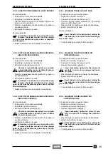
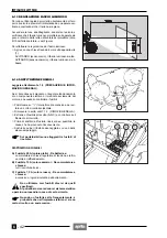
7.1.1 DESMONTAJE DEPOSITO COMBUSTIBLE
Lea con cuidado 1.2.1 (COMBUSTIBLE), 1.4 (PRE-
CAUCIONES E INFORMACIONES GENERALES) y 4.1
(SERBATOIO CARBURANTE).
Los vapores del combustible perjudican la sa-
lud. Anter de seguir adelante controle que el
lugar donde trabaja tenga un adecuado cam-
bio de aire.
No inhale los vapores de combustible.
No fume ni utilice llamas libres.
No esparza el combustible en el ambiente.
PELIGRO DE INCENDIO Y/O DE EXPLOSIÓN
X
Coloque el vehículo sobre el caballete.
Deje enfriar el motor hasta que el mismo al-
cance la temperatura ambiente.
X
Desmonte el sillín, véase 7.1.3 (DESMONTAJE SI-
LLIN).
Es posible desmontar el depósito del vehículo
con o sin el combustible en el interior del mis-
mo. En el primero caso, antes de empezar con las si-
guientes operaciones, vacíe el combustible del depó-
sito, véase 4.2 (EVACUACION COMBUSTIBLE DEL
DEPOSITO Y DE LOS CARBURADORES).
X
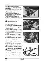
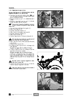
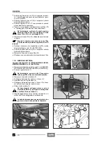
Ponga en “OFF” la palanca del grifo combustible (1).
Maneje con cuidado los componentes barni-
zados para no rayarlos o dañarlos.
X
Desconecte el conector eléctrico (2) del sensor reser-
va combustible.
X
Desempalme el tubo combustible (3) del grifo combus-
tible y tápelo.
X
Desempalme el tubo de desagüe de agua (4) del ta-
pón del depósito.
X
Destornille y saque el tornillo central (5).
X
Guarde el tampón de caucho (6), la arandela y, even-
tualmente, el casquillo.
X
+
Destornille y saque los tres tornillos (7).
X
Levante un poco el depósito (8) por la parte trasera y,
al mismo tiempo, extráigalo de los dos alojamientos
(en la parte delantera) tirándolo hacia atrás.
Al volverlo montar, controle que el depósito
entre correctamente en los respectivos aloja-
mientos de la parte delantera.
X
Desmonte, si es necesario, el grifo, véase 4.3 (DES-
MONTAJE GRIFO COMBUSTIBLE), la sonda nivel,
véase 4.4 (DESMONTAJE SONDA NIVEL COMBUS-
TIBLE) y el tapón, véase 7.1.2 (DESMONTAJE TA-
PON DEPOSITO COMBUSTIBLE).
Para mayores informaciones véase 4.1 (DE-
POSITO COMBUSTIBLE).
7.1.1 REMOVING THE FUEL TANK
Read 1.2.1 (FUEL), 1.4 (PRECAUTIONS AND GENER-
AL INFORMATION) and 4.1 (FUEL TANK) carefully.
Fuel vapours are noxious for the health.
Before proceeding, make sure that the room
in which you are working is properly venti-
lated.
Do not inhale fuel vapours.
Neither smoke, nor use naked flames.
Do not dispose of fuel in the environment.
RISK OF FIRE AND/OR EXPLOSION.
X
Position the vehicle on the stand.
Let the engine cool down until it reaches room
temperature.
X
Remove the saddle, see 7.1.3 (REMOVING THE SAD-
DLE).
It is possible to remove the tank from the vehi-
cle either with or without fuel inside it.
If the tank is full, before proceeding with the follow-
ing operations, empty it, see 4.2 (DRAINING THE
FUEL TANK AND THE CARBURETTORS).
X
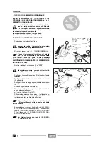
Rotate the fuel cock (1) to position “OFF”.
Handle the painted components with care and
avoid scraping or damaging them.
X
Disconnect the electric connector (2) of the low fuel
sensor.
X
Disconnect the fuel pipe (3) from the fuel cock and plug
it.
X
Disconnect the water dran pipe (4) from the filler cap.
X
Unscrew and remove the central screw (5).
X
Take the rubber element (6), the washer and if neces-
sary the bush.
X
+
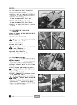
Unscrew and remove the three screws (7).
X
Slightly raise the rear part of the tank (8) and at the
same time withdraw it from its two seats (in the front
part), by pulling it backwards.
Upon reassembly, make sure that the tank fits
correctly into the relative seats in the front
part.
X
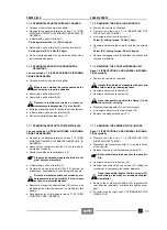
If necessary, remove the fuel cock, see 4.3 (REMOV-
ING THE FUEL COCK), the fuel level gauge unit, see
4.4 (REMOVING THE FUEL LEVEL GAUGE UNIT)
and the cap, see 7.1.2 (REMOVING THE FILLER
CAP).
For further information, see 4.1 (FUEL TANK).
Содержание Pegaso 650
Страница 1: ......
Страница 3: ...0 4 NOTE NOTES ANMERKUNGEN ...
Страница 4: ...1 1 1 2 3 4 5 6 7 8 INFORMAZIONI GENERALI INFORMACIONES GENERALES GENERAL INFORMATION ...
Страница 42: ......
Страница 69: ...3 1 1 2 3 4 5 6 7 8 MOTORE MOTOR ENGINE ...
Страница 90: ...3 22 MOTORE NOTE NOTAS NOTES ...
Страница 91: ...4 1 1 2 3 4 5 SISTEMA DI ALIMENTAZIONE SISTEMA DE ALIMENTACIÓN FUEL SYSTEM ...
Страница 116: ...4 26 SISTEMA DI ALIMENTAZIONE NOTE NOTAS NOTES ...
Страница 117: ...5 1 1 2 3 4 5 6 7 8 IMPIANTO DI RAFFREDDAMENTO SISTEMA DE REFRIGERACIÓN COOLING SYSTEM ...
Страница 130: ...5 14 IMPIANTO DI RAFFREDDAMENTO SISTEMA DE REFRIGERACIÓN COOLING SYSTEM NOTE NOTAS NOTES ...
Страница 131: ...6 1 6 1 2 3 4 5 6 7 8 IMPIANTO ELETTRICO INSTALACIÓN ELÉCTRICA ELECTRICAL SYSTEM ...
Страница 176: ...IMPIANTO ELETTRICO INSTALACIÓN ELÉCTRICA ELECTRICAL SYSTEM 6 46 NOTE NOTAS NOTES ...
Страница 177: ...7 1 1 2 3 4 5 6 7 8 CICLISTICA PARTE CICLO CHASSIS PARTS ...
Страница 226: ... 67 3 57 2 66 6 3 576 7 50 5827 3267 5 25 58 75 6 5 5 5 ...
Страница 242: ... 67 3 57 2 66 6 3 576 7 66 5 12 17 5 25 5 12 17 52 5217 5 ...
Страница 246: ... 67 3 57 2 66 6 3 576 7 70 5 12 3267 5 25 5 12 75 6 52 5 5 5 ...
Страница 272: ... 67 3 57 2 66 6 3 576 7 96 NOTE NOTAS NOTES ...
Страница 273: ...8 1 1 2 3 4 5 6 7 8 INFORMAZIONI PER LE RIPARAZIONI INFORMACIONES PARA LAS REPARACIONES REPAIRS ...
Страница 301: ...INFORMAZIONI PER LE RIPARAZIONI INFORMACIONES PARA LAS REPARACIONES REPAIRS 8 29 E F E F G H G H ...
Страница 302: ...INFORMAZIONI PER LE RIPARAZIONI INFORMACIONES PARA LAS REPARACIONES REPAIRS 8 30 I L I M L N M N ...
Страница 303: ...INFORMAZIONI PER LE RIPARAZIONI INFORMACIONES PARA LAS REPARACIONES REPAIRS 8 31 O P Q P O R Q R ...
Страница 310: ...INFORMAZIONI PER LE RIPARAZIONI INFORMACIONES PARA LAS REPARACIONES REPAIRS 8 38 NOTE NOTAS NOTES ...
Страница 311: ...INFORMAZIONI PER LE RIPARAZIONI INFORMACIONES PARA LAS REPARACIONES REPAIRS 8 39 ...

