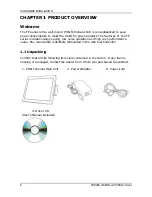
Wall Mount POS Terminal
FP-4266
User’s Manual
Edition: Jan 2015
Version 1.0
http://www.appostar.com
Страница 1: ...Wall Mount POS Terminal FP 4266 User s Manual Edition Jan 2015 Version 1 0 http www appostar com...
Страница 2: ...outlet on a circuit different from that to which the receiver is connected Consult the dealer or an experienced radio TV technician for help Declaration of Conformity These devices comply with part 15...
Страница 3: ...make improvements to this publication from time to time in the contents hereof without obligation of the manufacturer to notify any person of such revision or changes Copyright This work is copyright...
Страница 4: ...dropped damaged or broken The product may cause a fire or electric shock when it is used improperly Observe the safety measures at all times If the product is damaged immediately turn off the power an...
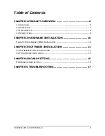
Страница 5: ...7 1 3 I O INTERFACE 8 1 4 SPECIFICATION 9 CHAPTER 2 HARDWARE INSTALLATION 10 MAGNETIC STRIPE READER MSR INSTALLATION 10 CHAPTER 3 SOFTWARE INSTALLATION 11 3 1 MOTHERBOARD DRIVER INSTALLATION 11 3 2 TO...
Страница 6: ...followin ged conta l Main Un CD ncluded ODUCT ount POS et the tren ng low n killfully em ng items a act the de it 2 T OVER S Termina nd for gre oise oper mbedded are conta ealer from Power A FP 4 RVI...
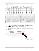
Страница 7: ...HARDWARE INSTALLATION FP 4266 Wall Mount POS Terminal 7 1 2 Appearance Front View Rear View 15 Touch LCD MSR module optional Attachable on both sides I O Cover MSR Cover...
Страница 8: ...for 2nd dis 0 Type A x 4 rt with RJ45 confusion er Remov e bracket No tch splay 4 5 n with the ve the cov t the HDD FP 4 o Por COM 1 COM 2 COM 4 Storage COM 5 CASH DRA e LAN port ver before D SSD ca...
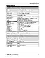
Страница 9: ...e Serial Port 4 x External COM Ports with 5V 12V selectable Cash Drawer Port 1 x RJ11 with DC 12V Standard 24V VGA Port 1 x VGA DB15 Speaker 2 x Integrated 1W stereo speaker Ethernet Port 1 x RJ45 10M...
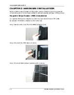
Страница 10: ...can be ins SR is insta he cover f he MSR ca SR module RDWAR are config isconnect der MS stalled on alled on th from the M able corre e in positio RE IN uration e ted to pre SR Inst both the he right...
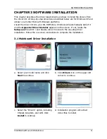
Страница 11: ...dows will automatically detect it and the Appostar Driver Installer appears on the screen If not locate the Setup exe file at CD and double click it to execute the one step driver installation Follow...
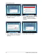
Страница 12: ...set Driver INF installed click No to continue f Select Install this driver software anyway in Windows Security window to continue the installation procedure g Select Install in Windows Security window...
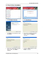
Страница 13: ...lick Peripheral Devices b Click Touch Panel c Click Next on the Welcome screen to continue d Ignore the Install PS 2 interface driver option Click Next to continue e Select the Install RS232 interface...
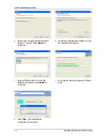
Страница 14: ...Multi Monitor System option Click Next to continue h Select the Destination Folder or use the default one listed i Type a Folder name or use the default one listed Click Next to continue j A progress...
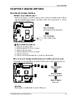
Страница 15: ...Operation 3 1 Pin 2 3 Close Clear CMOS data Clear CMOS Procedures 1 Remove AC power line 2 Set the jumper to Pin 2 3 close 3 Wait for five seconds 4 Set the jumper to Pin 1 2 close 5 Power on the AC 6...
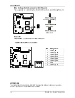
Страница 16: ...se Pin1 5V Default 4 3 Pin 3 4 Close Pin1 Ring 6 5 Pin 5 6 Close Pin1 12V Remark Max output 12V 500mA for each COM port JCOM2 Serial Port Connector Pin Assignment 1 COM2_RI 2 COM2C_DSR 3 COM2C_TXD 4 C...
Страница 17: ...e touch panel can detect the finger touch but the cursor is drifting use the touch tool from the Driver CD to execute calibration or draw test The Integrated VFD LCD display is not working properly 1...