

5
803809 Rev. 01
All 277 Volt units are furnished with a NEMA 7-20P,
20 Amp non-locking plug, and hence will require a
NEMA 7-20R receptacle to be installed in the heating
subbase.
NOTE:
These installations are not “cord connected”
units; they are permanently connected per the National
Electrical Code. The plug and cord are considered to be
a “connector of convenience” in order to facilitate easy
removal of the chassis for servicing. The plug and cord
are suitably protected within the heating subbase.
WARNING:
To avoid property damage, bodily injury
or death, the unit must be used on a grounded power
supply only. The unit will be grounded through the
service cord plug and matching receptacle as long as
the branch circuit remains grounded.
DO NOT:
Change the length of the cord.
Bend the connector blades or otherwise alter
service cord plug configuration.
Use extension cords.
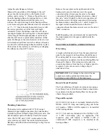
Wiring to Subbase
Remove the junction box cover plate. Punch out
the appropriate knock-out and anchor the electrical
supply conduit to the junction box. Connect the
power supply wires to the receptacle. Be sure to
properly ground the electrical supply to the
subbase and the receptacle using the two
Green
with Yellow Stripe
ground leads provided. Mount
the receptacle with the designated screws and re-
install the junction box cover plate.
CHASSIS INSTALLATION
Unpack heat/cool chassis from shipping carton.
Check for any shipping damage. Spin the fan wheels
manually to confirm free rotation. Inspect refrigerant
piping to ensure there is no damage or potential
chafing. Report any shipping damage to the carrier
immediately.
Check the interior of the installed wall sleeve. Clean
out any dirt or debris that may have accumulated.
Replace any air seals that are damaged or missing, if
applicable.
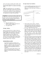
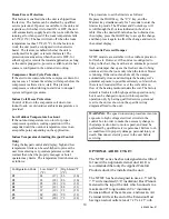
Heating/Cooling Chassis Installation
1.
Locate the
wall sleeve seal
shipped with the unit and
apply it to the top front flange of the wall sleeve,
running even with the bottom edge of the flange (see
illustration).
2.
Slide the chassis into the wall sleeve until firmly
seated against the seals. Push from the ends of the
front cover where they attach to the coil supports. Be
careful
NOT
to push the chassis from the electrical
box cover or middle of the front coil cover.
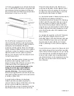
3.
The chassis must be level from side-to-side and
sloped toward the outdoors from front-to-rear in the
order of 1/8 inch per foot, once the chassis side
flanges are drawn up tight to the wall sleeve using the
four flange screws. A chassis slope downward
(backward toward the room) from outdoor-to-indoor
side is not permissible and must be corrected before
the unit is operated.
4.
There are vertical air seals at the rear of the unit that
surround the condenser outlet that will engage and
“seal” against the rear grille. However, in some cases,
such as when an extra deep wall sleeve is used, or
some other variation is encountered that prevents the
air deflectors from sealing against the outdoor grille,
then steps must be taken to add anti-recirculation
baffles to prevent hot condenser air from short-
circuiting back into the air intake/outdoor blower inlet
via the void space created in behind the outdoor grill.
5.
Position the chassis in the wall sleeve cabinet and
slide into place. Keep the chassis level, square, and
centered to prevent binding. The chassis must be
pushed into the wall sleeve until the side flange seals
of the chassis engage the sleeve. Alternately tighten
each of the four draw screws until the chassis is
drawn snugly into the sleeve. Do not over-tighten the
draw screws.