Apogee Instruments S2-432 Скачать руководство пользователя страница 1

APOGEE INSTRUMENTS, INC. | 

721 WEST 1800 NORTH, LOGAN, UTAH 84321, USA 

TEL: (435) 792-4700 | FAX: (435) 787-8268 | WEB: APOGEEINSTRUMENTS.COM 

Copyright © 2021 Apogee Instruments, Inc. 


OWNER’S MANUAL


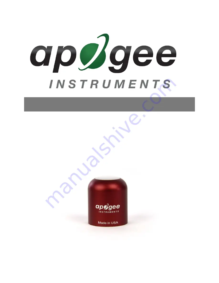
RED - FAR-RED SENSORS 

Models S2-432 

Rev: 2-Aug-2021


Содержание S2-432

Страница 1: ...UMENTS INC 721 WEST 1800 NORTH LOGAN UTAH 84321 USA TEL 435 792 4700 FAX 435 787 8268 WEB APOGEEINSTRUMENTS COM Copyright 2021 Apogee Instruments Inc OWNER S MANUAL RED FAR RED SENSORS Models S2 432 Rev 2 Aug 2021 ...

Страница 2: ...e of Compliance 3 Introduction 4 Sensor Models 5 Specifications 6 Deployment and Installation 8 Cable Connectors 9 Operation and Measurement 10 Maintenance and Recalibration 10 Troubleshooting and Customer Support 16 Return and Warranty Policy 17 ...

Страница 3: ...lectrical and electronic products with respect to the restriction of hazardous substances Please be advised that based on the information available to us from our raw material suppliers the products manufactured by us do not contain as intentional additives any of the restricted materials including lead see note below mercury cadmium hexavalent chromium polybrominated biphenyls PBB polybrominated ...

Страница 4: ...the wavelength ranges that drive the strongest responses in plants hence red far red sensor spectral responses should approximate the phytochrome absorption spectrum The primary application of red far red sensors is monitoring plant light environments including calculation of the red to far red ratio red photon flux density far red photon flux density and far red fraction far red photon flux densi...

Страница 5: ...itional models are covered in their respective manuals Model Signal S2 131 Self powered S2 431 SDI 12 S2 432 Modbus Sensor model number and serial number are located on the bottom of the sensor If you need the manufacturing date of your sensor please contact Apogee Instruments with the serial number of your sensor ...

Страница 6: ...iescent 37 mA active 42 mA Calibration Factor reciprocal of sensitivity Custom for each sensor and stored in firmware Calibration Uncertainty 5 Output Range Modbus Measurement Repeatability Less than 1 Long term Drift Less than 2 per year Non linearity Less than 1 up to 400 µmol m s Field of View 180 Wavelength Ranges 645 to 665 nm 5 nm Red 720 to 740 nm 5 nm Far red Directional Cosine Response 2 ...

Страница 7: ...spectral response measurements of six replicate red far red sensors red sensor is centered near 655 nm far red sensor is centered near 730 nm Spectral response measurements were made at 2 nm increments across a wavelength range of 600 to 800 nm in a monochromator with an attached electric light source Measured spectral data from each sensor were normalized by the measured spectral response of the ...

Страница 8: ...veling Plate is recommended To minimize azimuth error the sensor should be mounted with the cable pointing toward true north in the northern hemisphere or true south in the southern hemisphere Azimuth error is typically less than 1 but it is easy to minimize by proper cable orientation In addition to orienting the cable to point toward the nearest pole the sensor should also be mounted such that o...

Страница 9: ...ee directly to ensure ordering the proper pigtail configuration Alignment When reconnecting a sensor arrows on the connector jacket and an aligning notch ensure proper orientation Disconnection for extended periods When disconnecting the sensor for an extended period of time from a station protect the remaining half of the connector still on the station from water and dirt with electrical tape or ...

Страница 10: ... S2 432 Red Far red sensors For questions on the implementation of this protocol please refer to the official serial line implementation of the Modbus protocol http www modbus org docs Modbus_over_serial_line_V1_02 pdf 2006 and the general Modbus protocol specification http www modbus org docs Modbus_Application_Protocol_V1_1b3 pdf 2012 Further information can be found at http www modbus org specs...

Страница 11: ...t According to the Modbus protocol specification Holding Registers the type registers Apogee sensors contain are defined to be 16 bits wide However when making scientific measurements it is desirable to obtain a more precise value than 16 bits allows Thus several Modbus implementations will use two 16 bit registers to act as one 32 bit register Apogee Modbus sensors use this 32 bit implementation ...

Страница 12: ... left 46 Red detector millivolts shifted three decimal points to the left 47 Far red detector millivolts shifted three decimal points to the left 48 Ratio shifted one decimal point to the left 49 Percentage Far red shifted one decimal point to the left 50 Reserved for Future Use 51 device status 1 means device is busy 0 otherwise 52 Firmware version shifted one decimal point to the left Read Write...

Страница 13: ... even 59 number of stopbits 60 Red multiplier shifted two decimal points to the left 61 Red mV offset shifted four decimal points to the left 62 Far red multiplier shifted two decimal points to the left 63 Far red mV offset shifted four decimal points to the left 64 running average 65 heater status Registers marked with an asterisk cannot be written to unless a specific procedure is followed Conta...

Страница 14: ...function code 0x3 reading register address 0 Each pair of square brackets indicates one byte Slave Address Function Starting Address High Byte Starting Address Low Byte No of Registers High Byte No of Registers Low Byte CRC High Byte CRC Low Byte 0x01 0x03 0x00 0x00 0x00 0x02 0xC4 0x0B An example of a data packet sent from the controller to the sensor using function code 0x10 writing a 1 to regist...

Страница 15: ... or organic deposits are best removed using water or window cleaner and a soft cloth or cotton swab Salt deposits should be dissolved with vinegar and removed with a cloth or cotton swab Salt deposits cannot be removed with solvents such as alcohol or acetone Use only gentle pressure when cleaning the diffuser with a cotton swab or soft cloth to avoid scratching the outer surface The solvent shoul...

Страница 16: ...ce the cable length from the sensor to the controller should be kept short no longer than 20 meters For more information see section 3 3 5 in this document http www modbus org docs Modbus_over_serial_line_V1_02 pd RS 485 Cable Length If using an RS 485 serial interface longer cable lengths may be used The trunk cable can be up to 1000 meters long The length of cable from the sensor to a tap on the...

Страница 17: ...r factory The warranty does not cover equipment that has been damaged due to the following conditions 1 Improper installation or abuse 2 Operation of the instrument outside of its specified operating range 3 Natural occurrences such as lightning fire etc 4 Unauthorized modification 5 Improper or unauthorized repair Please note that nominal accuracy drift is normal over time Routine recalibration o...

Страница 18: ...anship Apogee Instruments will repair or replace the items free of charge If it is determined that your product is not covered under warranty you will be informed and given an estimated repair replacement cost PRODUCTS BEYOND THE WARRANTY PERIOD For issues with sensors beyond the warranty period please contact Apogee at techsupport apogeeinstruments com to discuss repair or replacement options OTH...

Отзывы: