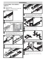
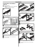
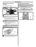
Aperto X-Box 550 Скачать руководство пользователя страница 8

Installation

8

Safety instructions

Caution!
Walls and ceiling must be solid and stable. 
Only install the operator on a correctly aligned door. 
An incorrectly aligned door could cause serious injury.


The operator may be installed, connected and commissioned 
by competent personnel only.


Do not move the door, if there are any people, animals or objects 
in the area of movement.


Keep children, disabled persons and animals away from the door.


Wear safety glasses when drilling the fastening holes.


Cover the operator and track during drilling to prevent dirt from entering 
the operator unit or operator track.


Use only approved fasteners (e.g. anchor 

fi

 ttings, screws). 

The fasteners must be suitable to the material of the ceilings and walls.


The supplied track supply line must not be shortened. 
Use only an original extension set to extend the line.


Live parts of the operator (voltage-carrying parts, e.g. C-track) 
may not be connected to the ground or with live parts or grounding 
conductors of other electrical circuits.

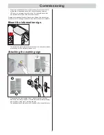
Safety-related preparation 
of the door

Caution!
The preparations must be made with the utmost care, 
since faulty preparations can lead to serious injuries 
as well as major damage to the operator and your garage.

Caution! Risk of death!
Remove all cords, straps and locks necessary to operate 
the door by hand.


Doors must be stable in themselves, since high traction and 
compression forces are encountered. Reinforce lighter doors 
made of plastic or aluminium if necessary before installation. 
Ask a specialist retailer for advice.


All existing mechanical door locks must be removed or made 
non-functional before beginning installation. 


Check that the door runs smoothly.


The door must be counterbalanced. 

Test:

   Half-open the door by hand. The door must remain in this 

position. If the door moves up or down, re-adjust the door 
mechanically. Ask a specialist retailer for advice.


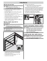
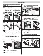
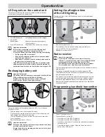
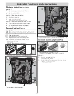
Check the distance between the highest running point of the door (THP, 
see Figure 11) and the lower edge of the C-track. The distance between 
the THP and the lower edge of the C-track must be between 5 mm and 
65 mm; the angle of the door arm must be max. 30° (see graphic 21). 
If the distance is less than this, the operator must be moved back and 
a longer push rod must be installed. Ask a specialist retailer for advice.


The travel path of the operator must be free of obstacles. 
Obstacles must be properly removed before installation 
since collisions are a safety risk and can damage the operator. 


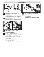
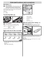
Adjusting the top roll of a sectional door

Lay the emergency release outside

Caution!
Most garages do not have a separate entrance (e.g. slip door). 
That is why the emergency release on the operator must 
be led outside to make it possible to open the door from 
outside in the event of a power failure or door defects. 
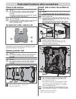
To do so, use the Bowden cable (18) or a release lock (19), 
which is not included in delivery. 
(See accessory instructions for installation) 

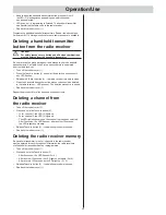
Installing slip door safety device

Caution!
If a slip door is in set into the door, but not a slip door safety 
device, a slip door safety device (20) must be installed. 
(See accessory instructions for installation).

Installation

Содержание X-Box 550

Страница 1: ...X Box 550 X Box 800 EN TRANSLATION OF THE ORIGINAL INSTALLATION AND OPERATING MANUAL 46725V001 422016 0 DRE Rev C_EN...

Страница 2: ...afety instructions 18 Opening the door 18 Closing door 18 Emergency release 18 Control unit reset 18 Intermediate stop 18 Safety stop 1 power cut off 18 Safety stop 2 safety input 18 Overload protecti...

Страница 3: ...in slip door you must install an emergency release release lock or Bowden cable that can be operated from outside Radio remote control The remote control must only be used for devices and systems in...

Страница 4: ...x General Rated voltage 24 V DC Lighting Integrated LED lighting Operational temperature range 10 C to 45 C IP code IP 20 Working environmental emissions value 75 dBA operator only Operator 550 800 Ma...

Страница 5: ...5 14 17 15 Item Name Quantity 14 Control unit with button and LED light field 1 15 Battery units left and right 2 16 Support rail centre housing is already installed on the track 1 17 Charger 1 Cautio...

Страница 6: ...ty EMC interference resistance EN 60335 2 95 04 2011 General safety requirements for household and similar electrical appliances Part 2 Particular requirements for operators for vertically moving gara...

Страница 7: ...tely mandatory if there is not a separate access point Slip door Pass door Built in pass door Caution If a slip door in set into the door a slip door safety device 20 must be installed Not included in...

Страница 8: ...cessary before installation Ask a specialist retailer for advice All existing mechanical door locks must be removed or made non functional before beginning installation Check that the door runs smooth...

Страница 9: ...disabled depending on the design of the door it could be possible to manually raise the door approx 50 mm To counteract this spring catches can installed to lock the door in addition to the operator T...

Страница 10: ...3 1 1 2 4 Push trolley 1 onto C track 2 Insert two C track parts 1 in the connecting sleeve 2 up to the stop position C A B 90 D a c 90 b 1 2 3 4 5 6 V V 5 Attach tensioner 1 to chain 2 and turn it 9...

Страница 11: ...2 1 3 1 1 2 4 Push trolley 1 onto C track 2 Insert two C track parts 1 in the connecting sleeve 2 up to the stop position a c 1 6 2 3 4 5 90 b 5 Attach tensioner 1 to chain 2 and turn it 90 Insert co...

Страница 12: ...M VM 13 The operator can be mounted on the header S or on the ceiling D Measure the front of the centre of the door VM and mark on the door and on the lintel or ceiling Caution Wear safety glasses whe...

Страница 13: ...cy unlocking cord N The carriage 1 is unlocked Tighten screw 8 on header fitting Slide the carriage 1 all the way to the front 3 with the connecting rod 2 If necessary loosen guide idler 4 Align door...

Страница 14: ...t yet connect the XLR plug of the operator to the X Box Caution Note the wall thickness of the garage 1 72 m 23 Mark horizontal holes for the support rail on the wall drill 4 holes minimum height of 1...

Страница 15: ...heck the following Have all mechanical door locks been removed Can the emergency release be activated from outside using a Bowden cable or release lock Important information When opening and closing t...

Страница 16: ...he guide idlers Check whether the door opens and closes completely If this isn t the case then the running path must be adjusted Activate command initiator e g button handheld transmitter once Door op...

Страница 17: ...imum of 112 storage locations for each radio receiver are available Mount the information sign N 46502V000 172006 0 OCE_Rev A The information sign concerning the function of the emergency release plea...

Страница 18: ...ave a built in slip door or the garage does not have a separate entrance you must install an emergency release a release lock or Bowden cable that can be operated from outside see accessories instruct...

Страница 19: ...esponds to the illustration Required charging time 6 12 hours Important information Disconnect the charger from the mains power and the battery unit after no later than 12 hours Charge the battery in...

Страница 20: ...ess the handheld transmitter button whose code should be deleted in the radio receiver LED goes out The deletion procedure is ended Reattach the rubber cover 1 Repeat the procedure for all buttons and...

Страница 21: ...the additional button Caution When actuating the button the drive must keep clear of the movement zone of the door and must have a direct view of it Important information Only necessary if an extra bu...

Страница 22: ...e control unit Important information A safety connection is no longer available A photo eye cannot be connected in parallel Button 2 can be used as needed for the following functions Defined opening a...

Страница 23: ...24 V max 0 1 A Terminal 9 DC 24 V Terminal 10 Earth Settings see Obstacle detection DIP 1 2 3 Pulse sequence of door movement DIP7 2 1 O N D I P 3 4 5 6 8 7 1x 1x 1x 1x STOP STOP DIP switch 7 OFF stan...

Страница 24: ...opens the door completely Button 2 only opens the door partially if it is closed If the door is to be completely opened with button 1 or partially opened with button 2 pressing button 2 again closes t...

Страница 25: ...plug to the solar module if necessary 1 2 3 4 5 6 7 Remove the four screws 1 on the front side Remove front housing 2 Caution First note the position of the plug and boards Make sure the board and plu...

Страница 26: ...ective Decommission the system and lock it to prevent reactivation Then contact customer service Photo eye if present Open close the door and interrupt photo eye Adjust the behaviour of the door as se...

Страница 27: ...o low Wipe force values and teach again Switch trigger incorrectly adjusted Adjust switch trigger see chapter Adjusting end switches Door incorrectly adjusted or defective e g spring shaft Have door a...

Страница 28: ...he chain see chapter Installation Displays on radio receiver Malfunction Possible cause Corrective action All LEDs flashing All memory locations occupied max 112 Delete any handheld transmitters that...

Отзывы: