21
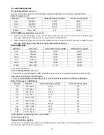
3.3 compatible mode table
PC Input Signal Reference Chart
Connect a computer to your TV set and set up the computer output signal in accordance with table below.
Default computer mode
Standard Resolution Horizontal
Frequency(KHz) Vertical
Frequency(Hz)
VGA 720×400
31.327
69.617
SVGA 800×600
37.879
60.317
XGA 1024×768
48.363
60.004
WXGA 1360
×
768*
47.72
59.799
DVI/PC HDMI Input Signal Reference Chart
1. When DVI port is being used: connect the DVI port of video device to your TV set with a DVI-to-HDMI line and
set up the output signal of the video device in accordance with table below.
2.
When HDMI port is being used: connect the HDMI ports of your computer and TV set with one HDMI wire and
set up the output signal of the video device in accordance with table below.
Default HDMI Mode
Standard Resolution Horizontal
Frequency(KHz) Vertical
Frequency(Hz)
VGA 640×480
37.879
60.317
VGA 720×400
31.327
69.617
SVGA 800×600
37.879
60.317
XGA 1024×768
48.363
60.004
SXGA 1280×1024
63.981
60.020
WXGA 1360
×
768*
47.72
59.799
*Recommended resolution
Video Input Signal Reference Chart
1. Connect the component signal or HDMI port of video device to your TV set and set up the output signal of the
video device in accordance with table below.
2. If your computer display card supports signals of video format then you can set up following output signal.
Default Component or HDMI Mode
Standard Resolution Horizontal
Frequency(KHz) Vertical
Frequency(Hz)
SD
720
×
480i
15.734 60
SD
720
×
480p
31.5 60
SD
720
×
576i
15.625 50
SD
720
×
576p
31.25 50
HD
1280
×
720p
37.5 50
HD
1280
×
720p
45 60
HD
1920
×
1080i
28.125 50
HD
1920
×
1080i
33.75 60
FHD
1920
×
1080p
56.25 50
FHD
1920
×
1080p
67.5 60
Video systems supported by the TV, video modes
PAL D/K B/G I; NTSC M
Standard Definition Interface
You can also enjoy traditional program by using a DVD player or VCR Player. Connect this equipment to your TV via
the Composite Input on the back of your TV.
Содержание LE32A3520/61
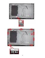
Страница 23: ...23 3 Remove the screws to remove MAIN BOARD and POWER BOARD 4 Remove the screws to remove BKT and AC COVER ...
Страница 24: ...24 ...
Страница 25: ...25 5 Remove the screws to remove SPEAKERS IR BOARD and KEY BOARD ...
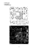
Страница 33: ...33 6 PCB Layout 6 1 Main Board 715G4629M01000004K ...
Страница 34: ...34 6 2 Power Board 715G4697P02001003H ...
Страница 35: ...35 6 3 Key Board 715G4846K01000004S 6 4 IR Board 715G4845R01000004S ...
Страница 37: ...37 8 Block Diagram ...
Страница 38: ...38 ...
Страница 58: ...58 10 Exploded View LE32A3520 61 ...


