19
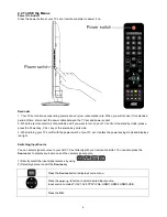
2.4 Front Panel Control Knobs
Controls & Connections
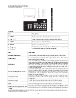
Controls
Item Description
1. VOL+/-
Press to increase or decrease the sound volume level.
2. CH
Press to select the next higher or lower program number.
3. MENU
Press to open or exit the OSD menu.
4. INPUT
Press to select the input source.
5.
(Power)
Switches the product on/standby or off. The product is not powered
off completely unless it is physically unplugged.
Connections
Item Description
AV(Audio/Video)Input
Connect audio (L/R)/video output from an external device to these jacks
Video Output
For connecting the Composite Video signal of the TV to other display
devices as their source signal.
HDMI Input
Connect a HDMI signal to HDMI port. The HDMI (High definition Multimedia
Input) connector provides Non-compressed and fully digital audio/video data
transmission between TV set and any HDMI audio/video devices, including
the set top box, DVD player, Blue-ray player, A/V receiver and computer.
You need an HDMI connection for viewing in 480i, 480p, 576i, 576p 720p,
1080i and 1080p modes.
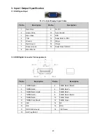
PC VGA IN (RGB)&PC Audio IN
It is used to Connect the video output port of a personal computer with a 15
pin D-sub (Analog RGB) VGA cable. It can be connected to other simulated
RGB devices. Connect separate audio cable between PC and TV to get
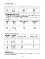
sound. Please refer to “Reference Table for computer input signal” for
signals that can be displayed.
Component input
Connect a component video (YPbPr) / audio (L/R) device to these jacks.
Component provides better picture quality than the composite video
connections.
TV Antenna input
The RF input is for connecting to the cable or VHF/UHF antenna.
USB
Connect USB storage device to enjoy Photos, Music and Videos.
SPDIF (Coaxial Digital Audio Out)
Connect an external sound system with coaxial cable to the SPDIF out jack
on the back of your TV to the SPDIF IN jack and to the amplifier or receiver.
* SPDIF
Sony/Philips Digital Interconnect Format. SPDIF is mostly used to transmit compressed multichannel audio from a
media player to an amplifier/receiver.
Содержание LE32A3520/61
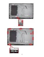
Страница 23: ...23 3 Remove the screws to remove MAIN BOARD and POWER BOARD 4 Remove the screws to remove BKT and AC COVER ...
Страница 24: ...24 ...
Страница 25: ...25 5 Remove the screws to remove SPEAKERS IR BOARD and KEY BOARD ...
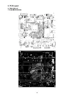
Страница 33: ...33 6 PCB Layout 6 1 Main Board 715G4629M01000004K ...
Страница 34: ...34 6 2 Power Board 715G4697P02001003H ...
Страница 35: ...35 6 3 Key Board 715G4846K01000004S 6 4 IR Board 715G4845R01000004S ...
Страница 37: ...37 8 Block Diagram ...
Страница 38: ...38 ...
Страница 58: ...58 10 Exploded View LE32A3520 61 ...


