background image

GB

27

SAFETY INSTRUCTIONS

Read the Operating Instructions carefully before use. 

Save these instructions for future reference. 

WARNING:

•  Disconnect the appliance from the mains before installation, maintenance and/or repair.
•  Installation, maintenance and/or repairs should be carried out by an authorised electrician and 

in accordance with these instructions.

•  The appliance is intended to be connected to 230 VAC 1-phase installations that comply with 

local regulations.

•  The appliance must be connected via a permanently installed automatic fuse with a minimum 

contact gap of 3 mm on all terminals.

•  Check before installation that the impeller och casing are undamaged.
•  There must be no foreign objects in the casing that could damage the fan blades.
•  The appliance must only be used as it is intended to be used and in accordance with these 

instructions. Do not make any modifications to the appliance.

•  The appliance is not intended to be used by persons (children or adults) with any form of 

functional disorders, or by persons who do not have sufficient experience or knowledge on how 
to use it, unless they have received instructions concerning the use of the appliance from 
someone who is responsible for their safety.

•  Keep children under supervision to make sure they do not play with the appliance.
•  Take the necessary precautions to prevent smoke, carbon monoxide and other flammable 

products from penetrating into the room through open flues or other fire safety devices.

•  Make sure that the air supply is sufficient for correct combustion and adequate chimney draught, 

to prevent backward flow.

•  The transported medium must not contain dust or other solid particles, sticky substances or 

fibres.

•  Do not use the appliance in explosive environments, e.g. in the vicinity of flammable liquids, 

gases or dust, or in environments that contain toxic or harmful substances.

•  Do not block the openings on the appliance to attempt to direct or adjust the air flow.
•  Do not sit or stand on the appliance, or place any objects on it.
•  Follow all the directives and safety instructions for best results and service-life.

Содержание 414099

Страница 1: ...äs bruksanvisningen noggrant innan användning Spara den för framtida behov BADRUMSFLÄKT SE EN BATHROOM FAN Operating instructions Translation of the original instructions Important Read the user instructions carefully before use Save them for future reference NO BADEROMSVIFTE Bruksanvisning Oversettelse av original bruksanvisning Viktig Les bruksanvisningen nøye før bruk Ta vare på den for fremtid...

Страница 2: ...ce być zagrożeniem dla środowiska i dla zdrowia Produkt należy oddać do odpowiedniego punktu składowania lub przynieść go do jednego ze sklepów gdzie przy zakupie nowego sprzętu bezpłatnie przyjmiemy stary tego samego rodzaju i w tej samej ilości Z zastrzeżeniem prawa do zmian W razie ewentualnych problemów skontaktuj się telefonicznie z naszym działem obsługi klienta pod numerem 22 338 88 88 www ...

Страница 3: ...nder eller av personer som inte har tillräcklig erfarenhet eller kunskap för att använda den såvida de inte har fått anvisningar gällande användande av apparaten av någon med ansvar för deras säkerhet Barn ska hållas under uppsikt så att de inte leker med apparaten Vidta nödvändiga åtgärder för att förhindra att rök kolmonoxid och andra förbränningsprodukter tränger in i rummet genom öppna rökgång...

Страница 4: ...n är avsedd för till och frånluftsventilation av lokaler som är uppvärmda vintertid Apparaten är avsedd för anslutning till luftkanal Ø 100 mm Luftriktningen i systemet ska motsvara pilen på fläkthöljet Drifttemperatur 1 45 C BETECKNINGAR I ELKRETSSCHEMA L Fasledare endast för nätmatning 230 V N Nolledare endast för nätmatning 230 V LT ST Manöverledare för fördröjningstimer QF Automatsäkring S Ext...

Страница 5: ...ningen i systemet ska motsvara pilen på fläkthöljet Steg 1 Bryt strömförsörjningen och förbered monteringsplatsen Steg 2 Avlägsna frontkåpan från apparaten Steg 3 Märk ut och borra fästhålen och montera apparaten Steg 4 Anslut fläkten till elnätet och ställ in fördröjning och luftfuktighetsgivare om så behövs Steg 5 Sätt tillbaka frontkåpan Steg 6 Slå till automatsäkringen OBS Bilderna visar fläkt...

Страница 6: ...SE 6 ...

Страница 7: ...7 BETECKNINGAR I ELKRETSSCHEMA L Fasledare endast för nätmatning 220 240 VAC N Nolledare endast för nätmatning 220 240 VAC LT ST Manöverledare för fördröjningstimer QF Automatsäkring S Extern strömbrytare ...

Страница 8: ...SE 8 ...

Страница 9: ... Fläkt med fördröjningstimer T1 startar vid inställd fördröjning efter att den externa strömbrytaren till exempel belysningsströmbrytaren slutits och manöverspänning lagts på plinten LT ST Startfördröjningen kan ställas in i två områden 10 till 90 sekunder och 2 till 30 minuter Inställningsområde väljs med en bygling på timerkretskortet När manöverspänningen brutits fortsätter fläkten att gå under...

Страница 10: ...l in börvärdet för luftfuktighet genom att vrida potentiometern H medurs för att öka eller moturs för att minska tröskelvärdet för luftfuktighet VARNING Nätspänning föreligger i timerkretsen Koppla bort strömförsörjningen från fläkten före inställning Använd den medföljande plastskruvmejseln för att vrida potentiometrarna för inställning Använd inte metallföremål för att ställa in potentiometrarna...

Страница 11: ...er av personer uten tilstrekkelig erfaring med eller kunnskap i å bruke det med mindre de har fått anvisninger om bruk av apparatet av noen som er ansvarlig for deres sikkerhet Barn skal holdes under oppsyn slik at de ikke leker med apparatet Iverksett nødvendige tiltak for å forhindre at røyk karbonmonoksid og andre forbrenningsprodukter trenger inn i rommet ved å åpne sotrør eller andre brannsik...

Страница 12: ...et Apparatet er beregnet på tillufts og avtrekksventilasjon av lokaler som er oppvarmet på vinterstid Apparatet skal kobles til luftekanal Ø 100 mm Luftretningen i systemet skal tilsvare pilen på viftedekselet Driftstemperatur 1 45 C BETEGNELSER I KOBLINGSSKJEMA L Faseleder kun til nettspenning 230 V N Nulleder kun til nettspenning 230 V LT ST Styreledning til tidsforsinkelse QF Automatsikring S E...

Страница 13: ...ningen i systemet skal tilsvare pilen på viftedekselet Trinn 1 Bryt strømforsyningen og forbered monteringsstedet Trinn 2 Fjern frontdekselet fra apparatet Trinn 3 Marker og bor ut festehull Monter apparatet Trinn 4 Koble viften til strømnettet og still inn tidsforsinkelse og luftfuktighetsmåler om nødvendig Trinn 5 Sett tilbake frontdekselet Trinn 6 Slå på automatsikringen OBS Bildene viser vifte...

Страница 14: ...NO 14 ...

Страница 15: ...O 15 BETEGNELSER I KOBLINGSSKJEMA L Faseleder kun til nettspenning 220 240 V AC N Nulleder kun til nettspenning 220 240 V AC LT ST Styreledning til tidsforsinkelse QF Automatsikring S Ekstern strømbryter ...

Страница 16: ...NO 16 ...

Страница 17: ...etter at den eksterne strømbryteren for eksempel lysbryteren sluttes og styrespenningen legges på splinten LT ST Forsinket start kan stilles inn i to områder fra 10 til 90 sekunder og fra 2 til 30 minutter Innstillingsområdet velges med en stropp på kretskortet for tidsforsinkelse Når styrespenningen blir brutt fortsetter viften å gå i innstilt tid 2 30 minutter Vifte med tidsforsinkelse og luftfu...

Страница 18: ...ler mot klokken for å øke eller minske terskelverdien for luftfuktighet ADVARSEL Kretsen for tidsforsinkelse er spenningssatt Koble viften fra strømnettet før innstilling av tidsforsinkelse Bruk den medfølgende plastskrutrekkeren til å dreie på potensiometrene Ikke bruk metallgjenstander til å stille inn potensiometrene det kan skade kretskortet VEDLIKEHOLD Vedlikehold skal utføres minst hver 6 må...

Страница 19: ...by nieposiadające wystarczającego doświadczenia lub umiejętności w zakresie obsługi urządzenia chyba że uzyskają wskazówki odnośnie do obsługi urządzenia od osoby odpowiedzialnej za ich bezpieczeństwo Dzieci powinny przebywać pod nadzorem aby nie bawiły się urządzeniem Podejmij wszelkie niezbędne środki aby zapobiec przedostawaniu się dymu tlenku węgla i innych produktów spalania do pomieszczenia ...

Страница 20: ...rza wlotowego i wlotowego w lokalach ogrzewanych w okresie zimowym Urządzenie należy podłączyć do kanału wentylacyjnego o średnicy 100 mm Kierunek przepływu powietrza powinien być zgodny ze strzałką na obudowie wentylatora Zakres temperatury pracy 1 45 C OZNACZENIA W SCHEMACIE OBWODU ELEKTRYCZNEGO L Przewód fazowy tylko do zasilania 230 V N Przewód zerowy tylko do zasilania 230 V LT ST Przewód ste...

Страница 21: ...n być zgodny ze strzałką na obudowie wentylatora Krok 1 Odłącz zasilanie i przygotuj miejsce montażu Krok 2 Zdejmij przednią obudowę z urządzenia Krok 3 Wyznacz i wywierć otwory montażowe i zamontuj urządzenie Krok 4 Podłącz wentylator do zasilania a w razie potrzeby ustaw także opóźnianie i czujnik wilgotności Krok 5 Załóż przednią obudowę z powrotem Krok 6 Włącz bezpiecznik automatyczny UWAGA Na...

Страница 22: ...PL 22 ...

Страница 23: ...ACIE OBWODU ELEKTRYCZNEGO L Przewód fazowy tylko do zasilania 220 240 V AC N Przewód zerowy tylko do zasilania 220 240 V AC LT ST Przewód sterujący wyłącznikiem opóźniającym QF Bezpiecznik automatyczny S Przełącznik zewnętrzny ...

Страница 24: ...PL 24 ...

Страница 25: ... zatrzymywany jest za pomocą przełącznika linkowego Wentylator z wyłącznikiem opóźniającym T1 uruchamia się o ustawionym czasie opóźnienia po włączeniu zewnętrznego przełącznika np przełącznika oświetlenia oraz ustawieniu napięcia sterowania na zacisku LT ST Opóźnienie uruchomienia można ustawić w dwóch zakresach od 10 do 90 sekund oraz od 2 do 30 minut Zakres regulacji wybiera się za pomocą zwork...

Страница 26: ...3 Ustaw wartość zadaną wilgotności przekręcając potencjometr H w prawo aby zwiększyć a w lewo aby zmniejszyć wartość progową wilgotności OSTRZEŻENIE W obwodzie wyłącznika występuje napięcie Przed przystąpieniem do regulacji odłącz wentylator od zasilania W celu regulacji potencjometrów użyj załączonego plastikowego śrubokrętu Nie używaj do tego celu metalowych przedmiotów gdyż może to uszkodzić ob...

Страница 27: ...ns children or adults with any form of functional disorders or by persons who do not have sufficient experience or knowledge on how to use it unless they have received instructions concerning the use of the appliance from someone who is responsible for their safety Keep children under supervision to make sure they do not play with the appliance Take the necessary precautions to prevent smoke carbo...

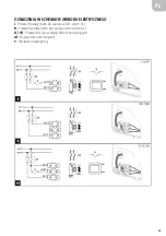
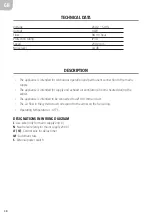
Страница 28: ...ce is intended for supply and exhaust air ventilaton of rooms heated during the winter The appliance is intended to be connected to a Ø 100 mm air duct The air flow in the system must correspond to the arrow on the fan casing Operating temperature 1 45 C DESIGNATIONS IN WIRING DIAGRAM L Live wire only for mains supply 230 V N Neutral wire only for mains supply 230 V LT ST Control wire for delay ti...

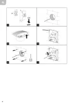
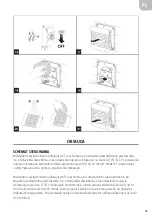
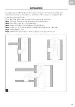
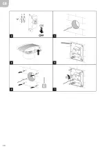
Страница 29: ...r flow in the system must correspond to the arrow on the fan casing Step 1 Disconnect the power supply and prepare the installation area Step 2 Remove the front cover from the appliance Step 3 Mark out and drill the screw holes and fit the appliance Step 4 Connect the fan to the mains and set a delay and humidity sensor if necessary Step 5 Replace the front cover Step 6 Switch on the automatic fus...

Страница 30: ...GB 30 ...

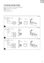
Страница 31: ...31 DESIGNATIONS IN WIRING DIAGRAM L Live wire only for mains supply 220 240 VAC N Neutral wire only for mains supply 220 240 VAC LT ST Control wire for delay timer QF Automatic fuse S External power switch ...

Страница 32: ...GB 32 ...
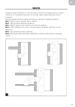
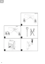
Страница 33: ...et delay after the external power switch e g light switch closes and control voltage is supplied to the terminal LT ST The start delay can be set to two intervals 10 to 90 seconds and 2 to 30 minutes The interval is selected with a jumper on the timer circuit board When the control voltage is disconnected the fan continues to run for the set time 2 to 30 minutes Fan with delay timer and humidity s...

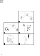
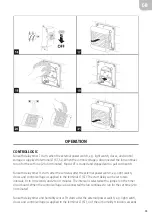
Страница 34: ...wise to decrease the threshold value for the air humidity WARNING The timer circuit is supplied with mains voltage Disconnect the power supply from the fan before installation Use the supplied plastic screwdriver to turn and adjust the potentiometers Do not use metal objects to set the potentiometers this could damage the circuit board MAINTENANCE Maintenance should be carried out at least once ev...

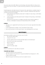
Страница 35: ... värmeåtervinning N A Maximalt luftflöde 98 m h Ljudnivå 54 dB A Maximal effekt 14 W Referensflöde 0 019 m s Referenstryckskillnad N A Specifik tillförd effekt 0 092 W m h Typ av styrning Manuell Maximalt inre läckage N A Maximalt yttre läckage 2 7 Årlig elförbrukning Kallt Medel Varmt 1 kWh m 1 kWh m 1 kWh m Årlig besparing av primär energi Kallt Medel Varmt 34 kWh m 17 kWh m 8 kWh m Kontakt www ...

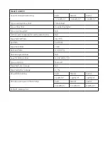
Страница 36: ...gjenvinning N A Maksimal luftstrøm 98 m h Lydnivå 54 dB A Maksimal effekt 14 W Referansestrøm 0 019 m s Referansetrykkforskjell N A Spesifikk tilført effekt 0 092 W m h Type styring Manuell Maksimal intern lekkasje N A Maksimal ekstern lekkasje 2 7 Årlig strømforbruk Kaldt Middels Varmt 1 kWh 1 kWh 1 kWh Årlig besparing av primær energi Kaldt Middels Varmt 34 kWh 17 kWh 8 kWh Kontaktinformasjon ww...

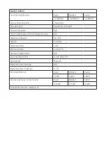
Страница 37: ...wietrza 98 m h Poziom hałasu 54 dB A Maksymalna moc 14 W Wartość odniesienia natężenia przepływu 0 019 m s Wartość odniesienia różnicy ciśnienia N A Energia wyjściowa 0 092 W m h Rodzaj sterowania Manualne Maksymalny wyciek ze środka N A Maksymalny wyciek z zewnątrz 2 7 Roczne zużycie energii elektrycznej Zimn Śred Ciepł 1 kWh 1 kWh 1 kWh Roczna oszczędność energii pierwotnej Zimn Śred Ciepł 34 kW...

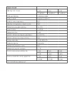
Страница 38: ...for recyling heat N A Maximum air flow 98 m h Noise level 54 dB A Maximum output 14 W Reference flow 0 019 m s Reference pressure difference N A Specific supplied output 0 092 W m h Type of control Manual Maximum inner leakage N A Maximum outer leakage 2 7 Annual power consumption Cold Medium Hot 1 kWh 1 kWh 1 kWh Annual savings of primary energy Cold Medium Hot 34 kWh 17 kWh 8 kWh Contact www jul...

Отзывы: