


YIG-tuned
Oscillator
There are two configurations of YIG-tuned oscillator
used in the 690XXB/691XXB—a 2 to 8.4 GHz oscil-
lator used in the 69017B/69117B model and a 2 to
20 GHz oscillator used in all other 690XXB/691XXB
models. The 2 to 20 GHz YIG-tuned oscillator actu-
ally contains two oscillators—one covering the fre-
quency range of 2 to 8.4 GHz and one covering the
frequency range of 8.4 to 20 GHz. Both oscillators
use a common internal amplifier.
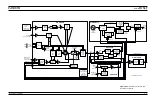
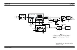
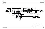
The YIG-tuned oscillator generates RF output sig-
nals that have low broadband noise and low spuri-
ous content. It is driven by the main tuning coil
current and bias voltages from the A14 YIG, SDM,
SQM Driver PCB and the FM tuning coil current
from the A11 FM PCB. During CW mode, the main
tuning coil current tunes the oscillator to within a
few megahertz of the final output frequency. The
phase-lock circuitry of the YIG loop then fine ad-
justs the oscillator's FM tuning coil current to make
the output frequency exact. In the 691XXB, fre-
quency modulation of the RF output is also accom-
plished by summing the external modulating
signals into the oscillator's FM tuning coil control
path.
When the 691XXB is generating broad-band analog
frequency sweeps (>100 MHz wide), the main tun-
ing coil current tunes the oscillator through the
sweep frequency range. Phase locking to fine adjust
the oscillator's output frequency is only done at the
bottom and top of the sweep ramp and on both sides
of each band switch point. Narrow-band analog fre-
quency sweeps (
£
100 MHz wide) in the 691XXB are
accomplished by summing the appropriate sweep
ramp signal into the oscillator's FM tuning coil con-
trol path. The YIG-tuned oscillator's RF output is
then swept about a center frequency that is set by
the main tuning coil current. Phase locking to fine
tune the output frequency is done at the center fre-
quency of the sweep.
Power Level
Control and
Modulation
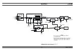
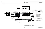
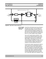
The RF output signal from the YIG-tuned oscillator
goes to connector J6 on the switched filter assembly.
In the switched filter assembly, the RF signal is
amplified then goes to the modulator. A portion of
the RF signal to the modulator is picked off and
coupled out via connector J5 to the Sampler for use
by the YIG loop circuitry.
2-20
690XXB/691XXB MM
FUNCTIONAL
RF DECK
DESCRIPTION
ASSEMBLIES
NOTE
For 691XXBs with Option 21A at
frequencies of
£
2.2 GHz, broad-band
a n a l o g f r e q u e n c y s w e e p s a r e
>25 MHz wide; narrow-band analog
frequency sweeps are
£
25 MHz.
Содержание 680 C Series
Страница 4: ......
Страница 5: ......
Страница 13: ...Figure 1 1 Typical Series 690XXB 691XXB Synthesized CW Signal Generator Model 69187B Shown ...
Страница 61: ......
Страница 97: ......
Страница 205: ......
Страница 207: ......
Страница 221: ......
Страница 225: ......
Страница 241: ......
Страница 259: ......
Страница 275: ......
Страница 285: ......
Страница 289: ......
Страница 299: ......
Страница 303: ......
Страница 315: ......


