


Chapter 2
Functional Description
2-1
INTRODUCTION
This chapter provides brief functional descriptions of the major sub-
systems that are contained in each model of the Series 690XXB/
691XXB Synthesized CW/Signal Generators. In addition, the opera-
tion of the frequency synthesis, automatic level control (ALC), and RF
deck subsystems is described so that the reader may better under-
stand the overall operation of the instrument. Block diagrams are in-
cluded to supplement the written descriptions.
2-2
690XXB/691XXB MAJOR
SUBSYSTEMS
The 690XXB/691XXB circuitry consists of various distinct subsystems
that are contained on one or more printed circuit board (PCB) assem-
blies or in microwave components located on the RF deck. The follow-
ing paragraphs identify the subsystems that make up the instrument
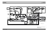
and provide a brief description of each. Figure 2-1 (page 2-6) is an
overall block diagram of a typical 690XXB/691XXB.
NOTE
Although identical model numbers of the series 690XXB CW
generators and series 691XXB signal generators contain the
same major subsystems, there are some functional differ-
ences between them. These functional differences result
fromthe series 691XXB having the additional capability of
producing analog frequency sweeps and AM, FM, and
square wave modulation of the RF output signal. Functional
differences between the series are noted in the following de-
scriptions where applicable.
Digital
Control
This circuit subsystem consists of the A17 CPU and
A16 CPU Interface PCBs. The central processor unit
(CPU) is the main controller for the 690XXB/
691XXB. This controller directly or indirectly con-
trols all functions of the instrument. The CPU con-
tains memory that stores the main operating system
components and instrument firmware, instrument
calibration data, and front panel setups in the
power-off condition. It has a GPIB interface that
allows it to communicate with external devices over
the GPIB and a serial interface to a serial terminal
port on the rear panel. The CPU is directly linked
via a dedicated data and address bus to the A2
Front Panel PCB, the A9 PIN Control PCB, the A10
ALC PCB, the A11 FM PCB, the A12 Analog
Instruction PCB, the A14 YIG, SDM, SQM Driver
690XXB/691XXB MM
2-3
Содержание 680 C Series
Страница 4: ......
Страница 5: ......
Страница 13: ...Figure 1 1 Typical Series 690XXB 691XXB Synthesized CW Signal Generator Model 69187B Shown ...
Страница 61: ......
Страница 97: ......
Страница 205: ......
Страница 207: ......
Страница 221: ......
Страница 225: ......
Страница 241: ......
Страница 259: ......
Страница 275: ......
Страница 285: ......
Страница 289: ......
Страница 299: ......
Страница 303: ......
Страница 315: ......


