


4-11
ALC BANDWIDTH
CALIBRATION
This procedure provides the steps necessary to perform ALC Band-
width calibration. The ALC Bandwidth is adjusted to compensate for
gain variations of the modulator. The adjustment is performed for
each frequency band. This provides a more consistent bandwith
throughout the frequency range of the instrument.
Equipment
Setup
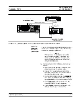
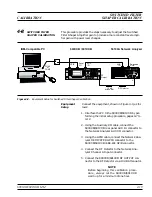
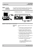
Connect the equipment, shown in Figure 4-7, as fol-
lows:
1. Interface the PC to the 690XXB/691XXB by per-
forming the initial setup procedure, pages 4-7 to
4-12.
NOTE
Before beginning this calibration proce-
dure, always let the 690XXB/691XXB
warm up for a minimum of one hour.
Bandwidth
Calibration
The following procedure lets you (1) calibrate the
ALC bandwith and (2) store the calibration data in
non-volatile memory (EEPROMs) on the A17 CPU
PCB.
1. Enter the ALC Bandwidth calibration routine as
follows:
a. At the
$
prompt on the PC display, type:
calterm 110
and press <ENTER>.
The
$
prompt will appear on the screen when
the ALC Bandwidth calibration is complete.
(This can take up to 15 minutes depending on
the frequency range of the 690XXB/691XXB.)
4-28
690XXB/691XXB MM
S e r i a l
I / O
6 9 0 X X B / 6 9 1 X X B
C O M 1
o r
C O M 2
I B M - C o m p a t i b l e P C
Figure 4-7.
Equipment Setup for ALC Bandwidth Calibration
ALC BANDWIDTH
CALIBRATION
CALIBRATION
Содержание 680 C Series
Страница 4: ......
Страница 5: ......
Страница 13: ...Figure 1 1 Typical Series 690XXB 691XXB Synthesized CW Signal Generator Model 69187B Shown ...
Страница 61: ......
Страница 97: ......
Страница 205: ......
Страница 207: ......
Страница 221: ......
Страница 225: ......
Страница 241: ......
Страница 259: ......
Страница 275: ......
Страница 285: ......
Страница 289: ......
Страница 299: ......
Страница 303: ......
Страница 315: ......


