background image

000-015-480 Issue 5 

22

nd

 May 2017 

Anite S-CORE Getting Started Guide 

Page 44 of 47 

Commercial In Confidence 

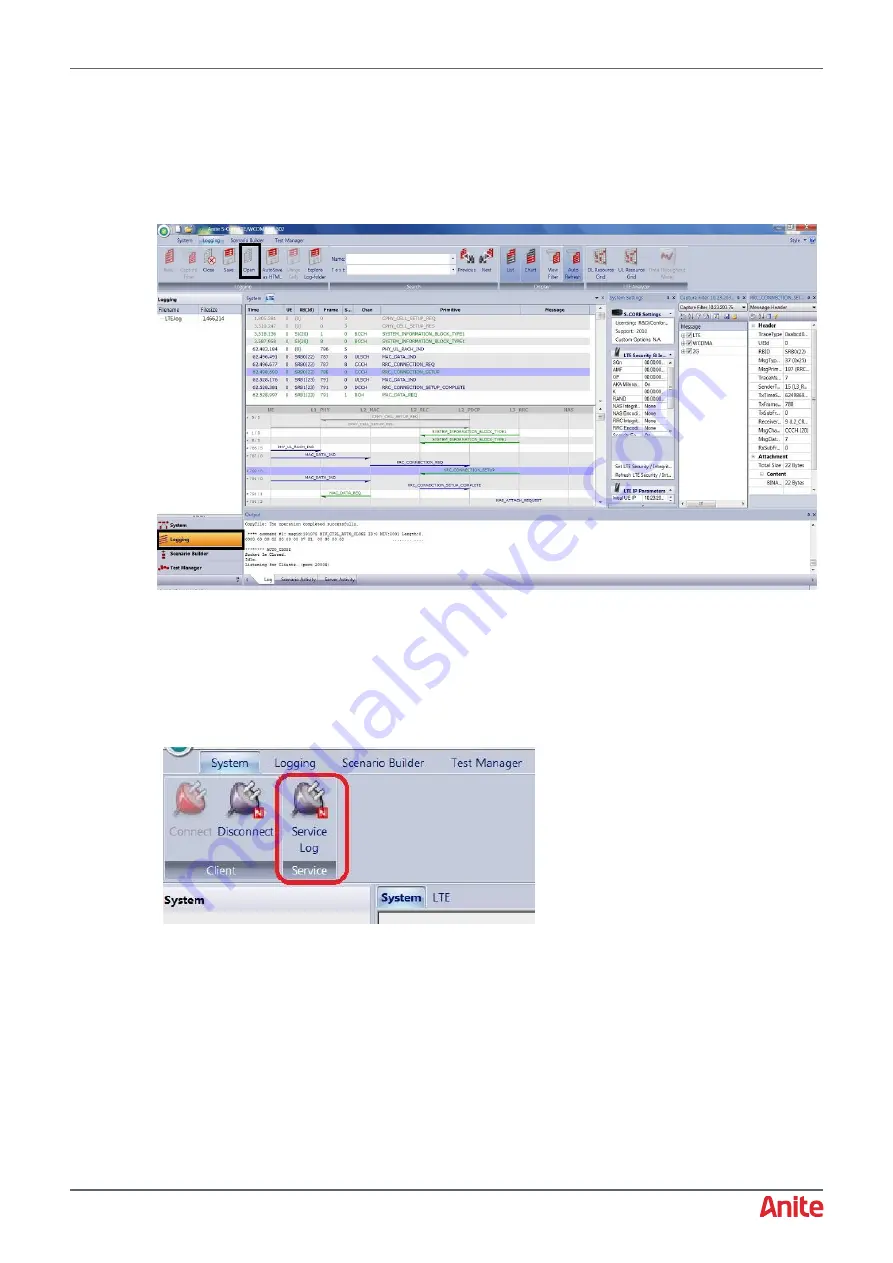
You can also view saved RF logs as follows: 

1. 

Display the RF Tracer by selecting to the 

Logging

 tab. 

2. 

Click 

Open

 from the menu, then select the RF log file (displayed in above example: LTE_VZW-

VoWiFi-05.15_2017_04_03_14_02_59). 

The log is then displayed in the window as shown below. 


7.4


Collecting Service Logs 

Service logs are used by Customer Support for analysis when you experience RF issues during test 
cases. 

At the end of any test cases where you experience RF issues:  

1. 

Click on the System tab, then click Service Log from the menu.  


2. 

Save the log to a local directory and send the service logs to Customer Support. 


Содержание S-CORE

Страница 1: ...uy your excess underutilized and idle equipment along with credit for buybacks and trade ins Custom engineering so your equipment works exactly as you specify Critical and expedited services Leasing R...

Страница 2: ...WWW ANITE COM Keysight Technologies 2012 2017 Commercial in Confidence ANITE S CORE APPLICATION TESTING GETTING STARTED GUIDE 22ND MAY 2017 000 015 480 ISSUE 5...

Страница 3: ...the Anite Help Desk and to download the latest software releases please log in to myKeysight On the myKeysight home page in the Quick Links box click the link for the Anite Help Desk or click Keysight...

Страница 4: ...ing The S CORE GUI 16 3 4 Updating software packages 17 3 5 Installing the S CORE External RF Controller 18 4 START TESTING USING S CORE 20 5 CONTROLLING RADIO ACCESS TECHNOLOGIES FROM THE GUI 25 5 1...

Страница 5: ...TP Link Router IP Address 46 APP B GLOSSARY 47 Table 1 Front view panel 6 Table 2 Rear view panel 8 Table 3 TP Link Router panel 10 Table 4 Anite WLAN Test Accelerator panels 11 Table 5 Test System P...

Страница 6: ...one test platform with an integrated LTE IMS radio and network subsystem and it includes an application test suite a rich and fully featured user interface and a wide portfolio of test case packages e...

Страница 7: ...tor LED green indicates that a session has been established with an external connection The LED will be green as long as the session remains connected LED off indicates that no session has been establ...

Страница 8: ...ce use 8 Power Button with LED Indicator Power on off switch LED off indicates that the test system has no power LED red indicates that the test system is in standby mode LED blinking green indicates...

Страница 9: ...nd signal trigger output 16 Trigger 1 I O LAN Ports 17 LAN Port 1 RJ 45 connection type for connecting S CORE test system with the TP Link Router or WLAN Test Accelerator Others 18 Status LEDs Display...

Страница 10: ...Router or WLAN Test Accelerator Others 25 Two USB Ports Used for connecting to the external devices 26 VGA Video Output Video output for connecting monitor with S CORE 10MHz Reference Connectors 27 10...

Страница 11: ...Holding down this button for 5 to 10 seconds will reset the wireless router back to the default TP Link factory settings It is recommended to contact support team before resetting router 3 LAN RJ 45...

Страница 12: ...g table Table 4 Anite WLAN Test Accelerator panels Button Port Description Power button To power the unit into and out of standby mode The button lights up when power is supplied to the unit The colou...

Страница 13: ...ORE test system Table 5 Test System PC requirements Item Requirement Adobe Flash Player Version 10 3 Processor Dual Core CPU Recommended Speed 2 5GHz Memory 2GB of RAM or higher Available Hard Disk Sp...

Страница 14: ...s section describes how to connect the S CORE unit Test System PC and WLAN Router TP Link Router or Anite WLAN Test Accelerator The S CORE test system can be configured using either a TP Link Router o...

Страница 15: ...of the Test System PC 5 Connect the S CORE to mains using a three prong AC power cord and into a grounded power socket The power input connector type IEC 322 is located on the back of the unit section...

Страница 16: ...2 3 Note It is important to connect both LAN cables before using the system 4 Connect a LAN cable from the Ethernet port 4 on the back of the WLAN Test Accelerator to the network card in the back of t...

Страница 17: ...PC as follows If Keysight provided the test system PC it will have Windows 7 with the latest updates and patches installed If you are using your own test system PC ensure that you have taken equivalen...

Страница 18: ...ould lead to abrupt power loss which may cause file system errors 3 4 Updating software packages Updating or installing new software packages can be performed in two different methods depending if the...

Страница 19: ...lation of the package you will be notified Reboot the system after 3 minutes to make sure installation of packages is ready 3 5 Installing the S CORE External RF Controller The Anite External RF Contr...

Страница 20: ...to select the Destination folder to which the application extracts the required files The location must be set to one of the following C Program Files x86 Anite S CORE Macros for 64 bit Windows PCs C...

Страница 21: ...and password The default Application Server IP Address Username and Password are listed below IP Address 10 23 205 xx IP of your Application Server Username admin Password Fen8Geng xx are the last tw...

Страница 22: ...ing Started Guide Page 21 of 47 Commercial In Confidence The applications available will be highlighted depending on the purchased packages Select the application you wish to test by pressing the Star...

Страница 23: ...Commercial In Confidence Enter application specific settings as required in application option window E g VOIP Options Network Type SCORE LTE Core Network Address 10 23 204 xx IP of signalling card P...

Страница 24: ...h to run from the list indicated as shown in this screen shot then click on the Add to campaign button Click on Close to go to the next screen In the main S CORE GUI user can switch on the RAT GERAN W...

Страница 25: ...which displays the PICS Pool window b On the PICS Pool window select the PICS file to use and click Set Active PICS c Click Close to close the dialog 2 Select the required test cases to run then clic...

Страница 26: ...ADIO ACCESS TECHNOLOGIES FROM THE GUI The three RATs available on the S CORE GERAN LTE FDD and WCDMA can easily be controlled from the S CORE GUI They can be found exactly under the Views Bar by right...

Страница 27: ...ular RAT click on the OFF button 5 2 RF sub system setup The test system needs setting up for the expected RF Power levels This setup should be as accurate as possible The most important parameters ar...

Страница 28: ...ly before switching on the RF cell The following sections display the Settings Options Windows for the three available RATs GERAN WCDMA and LTE Note Specifying an RF value that is too low can lead to...

Страница 29: ...ownlink reference power Lower default values when connecting directly DUT with the S CORE When setting the downlink reference power use a value for a good radio connection We recommend 30dBm as a plau...

Страница 30: ...uide P CSCF IP Address Application Server IP Address Refer to the System Configuration Document For detailed information about the settings please refer to the Anite S CORE Application Testing Operati...

Страница 31: ...good starting point would be 25 dBM according to 3GPP TS 36 101 a class 3 UE should be set to 23dBm 2dB The Rx Power should be set to the maximum possible power level and it is better to specify a sl...

Страница 32: ...attenuation that is slightly too low rather than too high Specifying a value that is too high can lead to a Layer 1 system error which requires the S CORE unit to be re booted EPS Attach Type Based o...

Страница 33: ...000 015 480 Issue 5 22nd May 2017 Anite S CORE Getting Started Guide Page 32 of 47 Commercial In Confidence PDN2 PDN4 tab...

Страница 34: ...n MS IP Address IP for mobile it should be configured in the same subnet as the S CORE For more information see the Anite S CORE Application Testing System Configuration Guide AP Name Please set the A...

Страница 35: ...tings Setting Description MCC MNC Mobile Country Code and Mobile Network Code that RAT will broadcast K value IMSI Information of test SIM card Refer to the System Configuration Document RAND 16 bytes...

Страница 36: ...alues when connecting directly to Device Under Test UL Reference Power Uplink reference power MS IP address IP for mobile it should be configured in the same subnet as the S CORE DNS IP address User c...

Страница 37: ...age backup the existing LTE cell settings of the single cell RF stack as follows 1 Log in to the S CORE GUI 2 Right click on LTE Cell and select Settings of 1 3 Click Export and save the settings to a...

Страница 38: ...arted Guide Page 37 of 47 Commercial In Confidence 4 Click Upgrade to display the Instrument Upgrade screen below 5 Click Browse and select the S CORE RF Stack Packager executable file downloaded in s...

Страница 39: ...e log in to S CORE GUI Now two cell options Cell1 and Cell 2 can be seen in S Core GUI To configure and enable the LTE cells 1 Right click on the first cell and select Technology LTE FDD LTE FDD as sh...

Страница 40: ...Cell1 settings 5 Import the sample file in the S CORE GUI and modify the following settings The serial number of the S Core unit Uplink and downlink power levels Path losses 6 When complete click Appl...

Страница 41: ...ported directly for cell settings in multicell RF stack They need to be updated manually 6 5 RF connection for multicell test cases Connect both RF output 1A and 1B from front panel of S CORE to UE wh...

Страница 42: ...cells as shown below 3 Apply the changes to the cell before switching it on as follows a Right click on the RF cell and click Settings to display the RF settings dialog b Click Apply to save the chan...

Страница 43: ...ch Tracer button on the toolbar This will open a separate logging window which traces the lower layer messages You will be able to view the message exchange in two views one as simple list view and th...

Страница 44: ...matically with start of test case and RF logs saved with test case logs in same folder To enable automatic RF tracing 1 Click on Local Options 2 Display the Ext Tools2 tab 3 Select the Auto Start Trac...

Страница 45: ...e displayed in above example LTE_VZW VoWiFi 05 15_2017_04_03_14_02_59 The log is then displayed in the window as shown below 7 4 Collecting Service Logs Service logs are used by Customer Support for a...

Страница 46: ...tting Started Guide Page 45 of 47 Commercial In Confidence APP A APPENDIX A1 S CORE Monitor GUI The following GUI is displayed on the monitor connected with the S CORE Using the monitor is optional It...

Страница 47: ...logged in click on the Network tab then the DHCP and DNS sub tab from the menu 4 Scroll down and click on Static Leases 5 Modify each of the listed IP Addresses as required Here is a configuration ex...

Страница 48: ...Service GSM Global System for Mobile Communications GUI Graphical User Interface I O Input Output IMSI International Mobile Subscriber Identity IP Internet Protocol LAN Local Area Network LED Light Em...

Страница 49: ...uipment Have surplus equipment taking up shelf space We ll give it a new home Learn more Visit us at artisantg com for more info on price quotes drivers technical specifications manuals and documentat...

Отзывы: