background image

C1

39

60

330

0_

2.f

m

- 15 - 

IT

AUS

DE

FR

ES

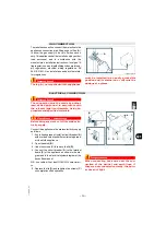
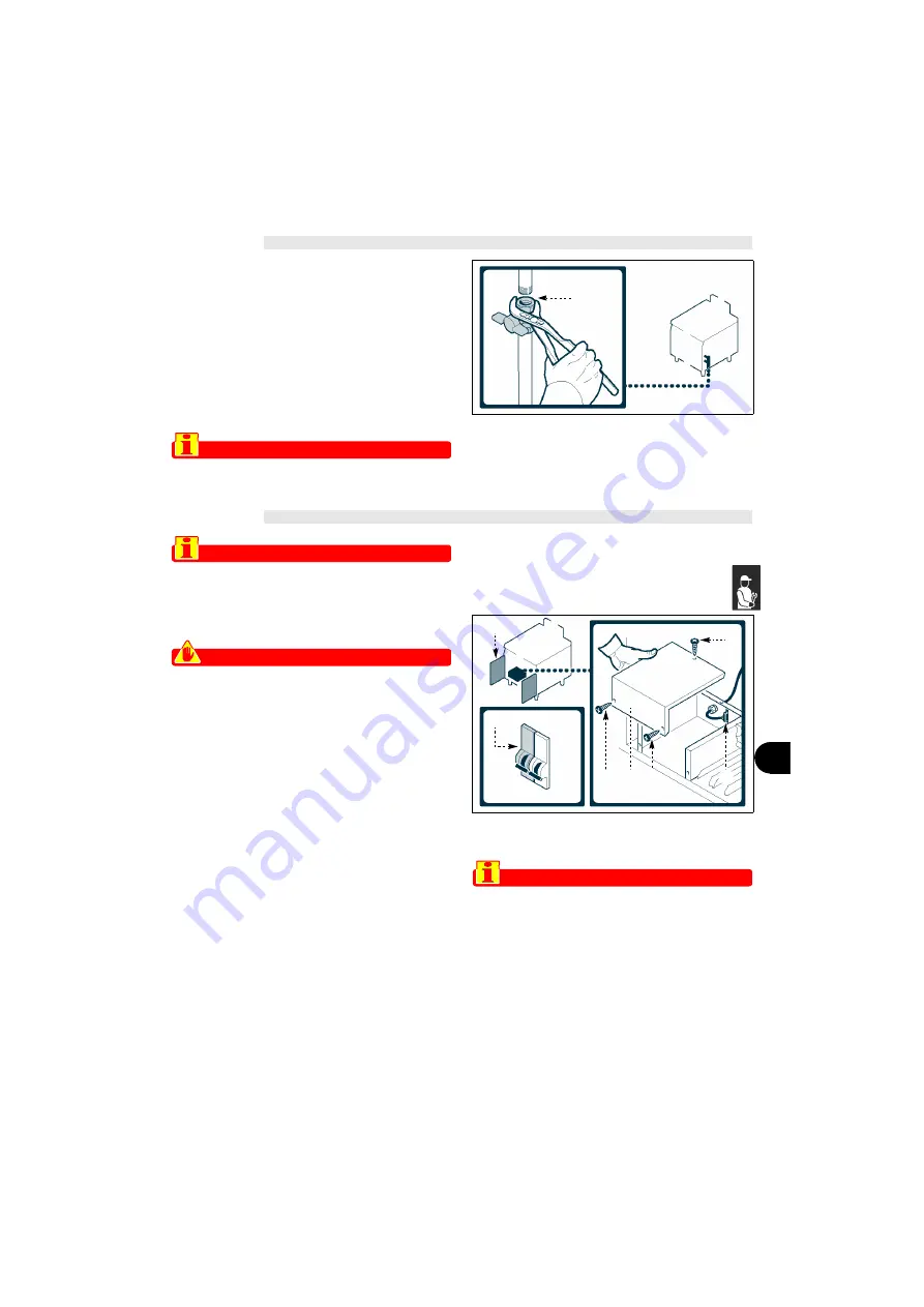
GAS CONNECTION 

To make the connection, connect the mains line to the
appliance's connection pipe, fitting a shut-off tap  (

A

),

to  allow  the  gas  supply  to  be  cut  off  when  neces-
sary.This  appliance  shall  be  installed  only by author-
ised  personnel  and  in  accordance  with  the
manufacture’s  installation  instructions,  local  gas  fit-
ting regulations, municipal building codes, water sup-
ply  regulations,  electrical  wiring  regulations,  AS
5601/AG 601 - Gas Installations and any other statu-
tory regulations.

Important

The tap (A), not supplied with the appliance,

must be installed in an easily accessible
position and its status (on or off) must be
obvious at a glance. 

ELECTRICAL CONNECTION

Important

The connection must be made by author-
ised, skilled personnel, in accordance with
the relevant legal requirements, using ap-
propriate and specified materials.

Caution - warning

Before doing any work, cut off the mains elec-
tricity supply.

Connect the appliance to the mains electricity supply

as follows.

1 - If not already present, install a circuit-breaker (

A

)

with overload cutout and differential safety break-
er close to the appliance.

2 - Open the hatch (

B

).

3 - Undo the screws (

C

) to remove the lid (

D

).

4 - Connect  the  circuit-breaker  (

A

)  to  the  terminal

board  (

E

)  of  the  appliance  as  shown  in  the  dia-

gram and in the electrical system diagram at the
back of the manual. 

N.B.: 

use cable with at  least H05RN-F characteristi-

cs.,

5 - Replace the lid (

D

) and retighten the screws (

C

)

on completion of the operation.

Important

When connecting, take care over the con-
nection of the neutral and earth lines; if
they are not connected correctly, the burn-
er does not light.

A

IDM-3960200230.tif

B

C

A

C

D

C

IDM-39603311900.tif

E

Содержание 1G1FR4G

Страница 1: ...C139603300_2 fm AUS GAS FRYER 1G1FR4G USE AND INSTALLATION MANUAL 3015270 ...

Страница 2: ...Contact for Sales or Service Angelo Po Catering Equipment Unit 4 15 17 Heatherdale Road Ringwood Victoria 3134 Telephone 03 9874 0440 Facsimile 03 9874 0330 ...

Страница 3: ... 16 Gas adjustingsolenoidvalve 17 Gas checkingpressure 10 Gas connection 15 Generaldescriptionofappliance 3 H Handling and installation recom mendationsfor 12 Handlingandlifting 12 I Identification of constructor and ap pliance 2 Installation and handling recommen dationsfor 12 Installationofappliance 13 Installationofdismantledparts 13 Installation of the flue deflector 14 L Lengthydowntimesofapp...

Страница 4: ...d ap ply its instructions to the letter The constructor supplies this information in its own language Ital ian but it may be translated into other languages to meet legal and or commercial requirements A littletimetakentoreadthisinformationwillallowthe preventionofriskstohealthandsafety andtherisk ofeconomiclosses Keep this manual in a clearly identified safe place throughouttheworkinglifeoftheapp...

Страница 5: ... appliance is designed andproducedforfrying foods intheprofes sionalcateringsector Main Parts A Frying well instainlesssteel B Fume exhaust vent Type A forremovalof the fumesgeneratedbytheburner C Temperature regulator knob forregulatingtheoil temperature D Mains light indicatesthattheapplianceisreceiving gas E Temperature light toindicatethatheatingoftheoilin thewellisinprogress F Basket hanger s...

Страница 6: ...ifthe flamegoesout C Safety thermostat cutsoffthegassupplyincaseof overheating Caution warning Make a daily check that the safety devices are properly installed and in good working or der SAFETY AND INFORMATION SIGNS The illustration shows the position of the signs provided A General hazard readthemanualcarefullybe forecarryingoutanyprocedure B General hazard describes the precautions to be adopte...

Страница 7: ...ty Even after you have read all the appropriate docu mentation ifnecessaryonfirstusecarryoutafewtrial operations to get to know the controls especially those used for switching on and off and their main functions Use the appliance only for the functions intended by themanufacturer Improperuseoftheappliancemay involvehealthandsafetyrisksandeconomiclosses All servicing operations requiring specific ...

Страница 8: ...may be caused by unpredict able environmental factors while others are due above all to the behaviour of users As well as receiving authorisation and appropri ate instruction if necessary the first time they use the appliance users must carry out a few simulated practice operations in order to get to know the controls and the main functions Use only as intended by the constructor and never tamper ...

Страница 9: ...lockwise pos b to the tem peraturerequired N B the temperature light E comes on to indicate that the oil is not at the working temperature the light goes out when the temperature is reached Turning off 1 Turn the knob A anti clockwise pos c to turn offtheburner N B the pilot light will remain on to allow the burner to be re lit 2 Openthehatch C 3 Presstheknob D andturnitclockwise pos g to turnofft...

Страница 10: ...ppedtorestorethegassupply 4 Closethehatch A LENGTHY APPLIANCE DOWNTIMES If the appliance is to be out of use for alengthy period proceedasfollows 1 turnoffthegassupplytap 2 clean the appliance and the surrounding areas thoroughly 3 spread a film of edible oil over the stainless steel surfaces 4 carryoutalltheservicingprocedures 5 leave the appliance uncovered and the cooking chambersopen USEFUL AD...

Страница 11: ...ac cess to all devices which might cause unex pected health and safety hazards if turned on At the end of each session of use and whenever necessary clean thewell seepage10 theburner seepage9 the appliance and the surrounding environment seepage9 Every100 working hourshaveskilled author ised personnel carry out the following opera tions acheckonthegaspressureandsystemtight ness acheckontheefficien...

Страница 12: ...theoil seepage8 5 Apply a food grade detergent to the inside of the well 6 Rinsethewellwithdrinkingwateranddrain 7 Applyaspecificproductorawaterandvine gar solution to the well to remove the deter gentresidues 8 Rinse emptyanddrythewell CHECKING GAS PRESSURE Tocarryoutthisoperation proceedasfollows 1 Turnoffthegassupplytap 2 Openthehatch A 3 Undothepressureconnectionscrew B 4 Connect the pressure ...

Страница 13: ...rofoperation Fault Causes Remedies Smellofgas Occasionalleakbecauseflame hasgoneout Turnoffthegassupplytapand ventilatetheroom Thepilotlightdoesnotignite Thesparkignitiondevicesarenot working Checkthattheignitiondevicesare ingoodworkingorder Lightby handwithanakedlight Contact the after sales serv ice Airinpipelinesduetolongperiod outofuse Makemoreattemptstolightthe flame Thepilotlightgoesout Thet...

Страница 14: ...ort The packaging carries all information necessary for loadingandunloading Whenunpacking checkthatall components are present in the correct quantities andareundamaged The packaging material must be properly dis posedofinaccordancewithlegalrequirements TRANSPORT Differentmeansoftransportmaybeused depending partlyonthedestination The chart shows the most commonly used alterna tives During transport...

Страница 15: ...ructions pag 14 and leave a minimum clearance of 5 cm from the rear of the appliance to the wall except if the wall the inter nalstructureanditscoatingisnon combustible Ifany internal part of the wall is made from a combustible material leave a 5 cm gap regardless of the external claddingonthewall INSTALLATION OF DISMANTLED PARTS The appliance is delivered with some components dismantled and they ...

Страница 16: ... in the lower holes of the flue 8 4 Fix the pivots 3 and 4 by means of nuts 6 and washer 7 5 Unscrew the screws 9 fixed on the flue 8 see Fig B 6 Insert the flue 8 see Fig C 7 Screw down the screws 9 to fix the flue on the appliance see fig D 8 Fit the heat protection 10 on the flue see Fig D 9 Fit the cast iron flue vent 11 at the top of the flue see Fig D INSTALLATION OF THE FLUE DEFLECTOR Fig A...

Страница 17: ... author ised skilled personnel in accordance with the relevant legal requirements using ap propriate and specified materials Caution warning Before doing any work cut off the mains elec tricity supply Connect the appliance to the mains electricity supply asfollows 1 If not already present install a circuit breaker A withoverloadcutoutanddifferentialsafetybreak erclosetotheappliance 2 Openthehatch ...

Страница 18: ...llows 1 Turnoffthegassupplytap A 2 Changetheburnernozzle seepage19 3 Changethepilotlightnozzle seepage19 4 Adjustthegassolenoidvalves seepage17 5 Remove the sticker from the nameplate and ap plythenewonetoidentifythegasbeingused Important On completion of the operation make sure that there are no gas leaks or mal functions If converting from Natural gas to Un iersal LPG make sure the Natural gas r...

Страница 19: ...eckthatthenameplatesspecifythecorrectgas forthecountryofuse After testing if necessary instruct the user in all the skills necessary for putting the appliance into opera tion in conditions of safety in accordance with legal requirements ADJUSTMENTS 8 RECOMMENDATIONS FOR ADJUSTMENTS Important Before making any type of adjustment acti vate all the safety devices provided and de cide whether staff at...

Страница 20: ... disconnect the pressure gaugeandrestoretheinitialconditionsaftercom pletingtheoperation Liquid gas 1 Turnoffthegassupplytap 2 Openthehatch A 3 Unscrewthecap D 4 Remove the adjuster screw E and the spring F andreplacethemwiththecap G suppliedonrequest 5 Screwthecap G fullydown 6 Restoretheinitialconditionsafter completingthe operation ADJUSTING BURNER PRIMARY AIR Tocarryoutthisoperation proceedasf...

Страница 21: ... OF THE BURNER NOZZLE Tocarryoutthisoperation proceedasfollows 1 Turnoffthegassupplytap 2 Openthedoor A 3 Unscrewthenozzle B andreplaceitwiththeone suitable for the type of gas in use see table at backofmanual 4 Closethedoor A REPLACEMENT OF THE PILOT LIGHT INJECTOR Tocarryoutthisoperation proceedasfollows 1 Turnoffthegassupplytap 2 Openthedoor A 3 Unscrewtheunion B 4 Extract the nozzle C and repl...

Страница 22: ...CT39603300_2 fm I ANNEXES Model Burner TotalGasconsumption Electrical connection 22MJ h NGN ULPG 1G1FR4G N 4 88 MJ h 88 MJ h 240V1 N 50Hz 50W CONNECTION CARD IDM 39603312300copia tif ...

Страница 23: ...1 Mainburnerinjectorsize 3 Pilotinjectorsize 4 Adjustingburnerprimaryair seepag 18 N G C 2 Pilot flame Primary areation GAS TPP 1 Supplypressure G C Ø 2 1 Ø 3 Ø 4 NGN 0 8 kPa 1 13kPa 88MJ h 2 25mm 0 40mm 26mm open ULPG 2 75 kPa 2 75kPa 88MJ h 1 25mm 0 25mm 26mm open ...

Страница 24: ... with ignitioncontact LH fryer 6 Electronic ignition device 7 Safety thermostat LH fryer 8 Thermocouple LH fryer 9 Switch with coaxial thermostat RH fryer 10 Mains power indicator light RH fryer 11 Thermostat indicator light RH fryer 12 Gas solenoid valve with ignition contact RH fryer 13 Safety thermostat RH fryer 14 Thermocouple RH fryer IDM 39603312600 tif 1 6 8 7 5 14 13 10 11 4 9 3 2 12 ...

Отзывы: