background image

User manual


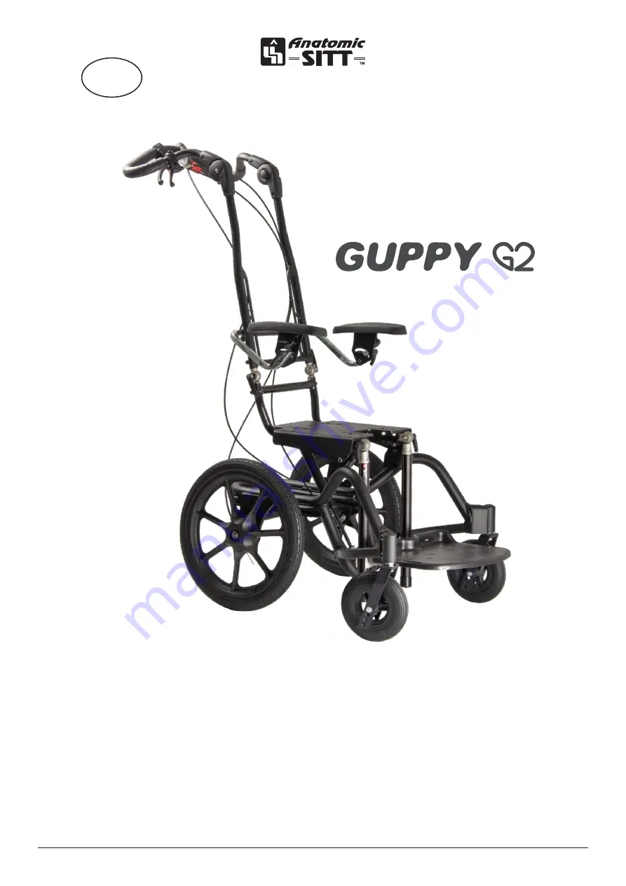
Zitzi Guppy G2

EN

ver

. 2.

0 - 20

20-04-

15

Содержание Zitzi Guppy G2

Страница 1: ...User manual Zitzi Guppy G2 EN ver 2 0 2020 04 15 ...

Страница 2: ...me 15 Mounting of the caster on a fork 15 Caster positioning 15 Adjusting of caster fork 16 Angle adjustment of caster fork 16 Brake 17 To use drum brake 17 Locking of wheels 17 Releasing wheels 17 Mounting of drum brake 18 Troubleshooting of drum brake 20 Parking brake 21 Mounting of parking brake 21 To use parking brake 21 Footrest 22 Mounting of footrest 22 Safety stop 22 Adjusting angle of the...

Страница 3: ...ty bracket 32 Using transportation brackets 32 Service and maintenance 33 Service intervals 33 Cleaning and washing instructions 33 Gas piston 33 Warranty 34 Combinations 34 Spare parts 34 Marking 34 Recycling 34 Reconditioning 35 Introduction 35 Cleaning 35 Finishing 35 Marking 35 Wheels 35 Paint 35 Stability 36 Tubular frame and details 36 Forks 36 Driving bow and push handle 36 Brakes 36 Foldin...

Страница 4: ...Maximum load weight is 75 kg Correspondence Zitzi Delfi Pro and its accessories are CE marked products A unique serial number is located on a label placed under the activation housing This serial number should be quoted in any correspondence regarding the product Crash tested approved Zitzi Guppy G2 is crash tested and approved according to ISO 7176 19 for 75 kg in a car Safety precautions If a se...

Страница 5: ...ved Place of label This product is manufactured by Anatomic SITT i Norrköping AB Postal address Anatomic SITT AB Box 6137 SE 600 06 Norrköping Street address Anatomic SITT AB Terminalgatan 1 SE 603 61 Norrköping Phone 46 11 161800 Email info anatomicsitt com Webb anatomicsitt com Instructions movies youtube com anatomicsitt Follow us on facebook com anatomicsitt ...

Страница 6: ...rt Mounting the seatplate The seat systems mounting plate is easily mounted on the chassis seat plate by use of four 4 screws washers and nuts in marked tracks A A NOTE For further information on mounting plates see the respective user manuals for the chosen seating system ...

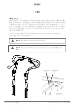
Страница 7: ...bow with one hand and push it down forward Release the slider A when you have reach the desired tilt To reset the seat angle to the original position press the slider A and drag the driving bow up to behind Tilt A Montering av negativ tilt Guppy Guppy har två olika lägen för tilt vilket ställs in med hjälp av hål under sittplattan Om kolven fästs in i hålet längst bak som på bild nedan erhålls til...

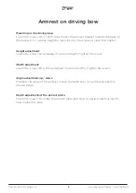
Страница 8: ... A and then tighten Height adjustment Losen the screws A and adjust to desired height Tighten the screws Width adjustment Losen the screws B a little and adjust to desired width Tighten the screws Angle adjustment up down To adjust the angle of the armrest loosen the hand lever C a little and adjust to desired angle Depth adjustment of the armrest plate Losen the screws D under the armrest plate a...

Страница 9: ...9 User manual Zitzi Guppy G2 www anatomicsitt com 46 11 16 18 00 D B A C ...

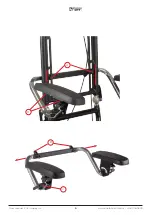
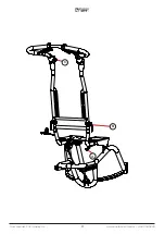
Страница 10: ...ng bow can be adjusted according to seating system Release the locking of the bow by loosening both levers B and adjust to the desired angle Then tigh ten both lever handles B Angle adjustment of driving bow handle To adjust the driving handle angle press the buttons C the inside of the frame joints and then adjust to the desired angle Folding of driving bow Losen both lever handles B and lower th...

Страница 11: ...11 User manual Zitzi Guppy G2 www anatomicsitt com 46 11 16 18 00 A B C ...

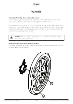
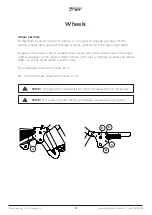
Страница 12: ...d hold the button B in the wheel center while you stick the axle into the chassis until it stops Release the press button B Secure that the wheel is installated properly by trying to pull it outwards without pressing the quick release button B Release the driving wheel with quick release To release the wheel press and hold the button B in the wheel center as you pull off the wheel from the chassis...

Страница 13: ...is seat plate To adjust the wheel in depth release four screws A on the underside of the wheel shaft and adjust to the desired depth Check with ruler or folding rule that the wheel shaft sits at the same depth on both sides 16 wheels are mounted in holes B C 20 22 and 24 are mounted in holes D E A B C E D NOTE Changing the wheelposition might increase the risk of tipping NOTE The screws should not...

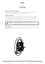
Страница 14: ...ting driving wheels and assembles according to separate user manual in the intended hole pattern on the side of the wheelchair frame with spacer washer screw nut and hub shaft The hand control is fitted with the supplied details on the driving handle Using E drive E drive makes Guppy an attendent operated electrical wheelchair and controlled by a hand control l NOTE For more detailed information a...

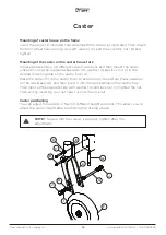
Страница 15: ...s Caster Mounting of the caster on the caster house fork Choose between four 4 different castors positions and then mount the caster wheel F using the supplied wheel axle G washer H and lock nut I in the desired mounting hole on the castor fork K Place the caster F in the castor fork K according to the picture Place a washer on the wheel axle G and then insert it into the desired hole on the casto...

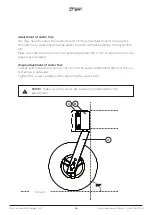
Страница 16: ...without adjusting the caster fork A Make sure that the position of the caster attachment B is 90 in proposition to the ground as illustrated Angle adjustment of caster fork Loosen and rotate the eccentric nuts C on the caster attachment B until the cor rect angle is obtained Tighten the screws properly after adjusting the caster fork Ground 90 90 C B A NOTE Make sure the screws are properly tighte...

Страница 17: ...ng lever B forward to desired position Releasing the brakes To release locking of a wheel press the brakehandle A and the locking device B will release automatically Then let go of the brakehandle A A This document is the property of Anatomic Sitt AB The information in this or parts thereof may NOT be copied altered or in other ways used unless previously allowed by Anatomic Sitt AB Nor may the in...

Страница 18: ...through the hole for rotation lock in the brake drum through the small spacer D and through the holes in the frame side Attach with washer E and nut F on the inside of the frame side plate t Tighten both nuts B and F so that the brake drum is securely tightened Take the quick release axle with the wheel and push until the wheel attaches Test by pulling the wheel slightly outwards without pressing ...

Страница 19: ...19 User manual Zitzi Guppy G2 www anatomicsitt com 46 11 16 18 00 C A B F E D ...

Страница 20: ...w tension try to tens it by loosen the screw C and then tighten again If the adjustment is not enough try the following quick setup guide to re tighten the brake cables 1 Tighten the screw C to its bottom position 2 Loosen the nut D 3 Squeeze the brake by lifting the drum brake arm E and move the nut D further up the wire 4 Tighten the nut D and adjust the tension with the screw C ...

Страница 21: ...e supplied screws A spacers B and nuts C If necessary adjust the parking brake D by loosening the screw E and then move the parking brake D forward or backward in the track Tighten the screw E when desired position is reached To use the parking brake Lock the parking brake D by pushing the parking brake lever forward Pull the parking brake lever back to release the parking brake Parking brake D E ...

Страница 22: ...n the seat part plate it is possible to adjust the footrest at the knee joint Loosen the levers E slightly and adjust the footrest to the desired angle Tighten the levers Safety stop Safety stop D in the form of a rail pin is mounted in the bottom of footrest profile The safety stop can also be used to find back to a preset height position Adjusting the height of the footrest When the footrest is ...

Страница 23: ...ootrest plate and its brackets downwards Mount the calf support by pushing the rail pins C into the footrest stay adjust to the desired height and tighten the screws E Reassemble the footrest and it s end cap G Adjusting the height To adjust the height of the calf support loosen the screws E slightly and adjust to desired height Tighten the screws E Adjusting the width To adjust the width of the c...

Страница 24: ...ction first loosen the screws B and C and adjusts to the desired position Tighten the screws B and safety lock the position with screw C Footrest brackets NOTE The suspension resistens can be adjusted by turning the screw in the spring package F Fixed footrest brackets 1 To adjust the height loosen lever A slightly and adjust the footrest to desired height Tighten the lever Suspended footrest adap...

Страница 25: ...25 User manual Zitzi Guppy G2 www anatomicsitt com 46 11 16 18 00 A A A B C A A A A E D F A B A C A B 1 2 2 3 4 4 4 3 3 ...

Страница 26: ...desired height and tighten lever knob E Use the screws F and G to set the desired height and width of the footrest The plastic stay H on the high edge footrest must be passed through the track I in the footrest plate Finish by mounting the included cushion and check that all screws are tightly tightened NOTE After adjusting the desired height the plastic stay H can be cut or heated under the footr...

Страница 27: ...ighten the screws Then finish by putting on nut covers D Using the anti tipper The anti tip should be used for a safer and secure usage of the chassis It can easily be folded when not in use by carefully stepping down the anti tip and turn it aside When deactivating try to step on the anti tip so close to the anti tip attachment as possible Make sure to turn the anti tipper until you hear a click ...

Страница 28: ... of the screws B from the outside Using the stepbar The stepbar facilitate the raising of the front chassis when it is necessary eg at side walks Push the stepbar with your foot while holding the driving handle and gently pull the chassis backwards to free up some space under the castors A B NOTE The stepbar is mounted on the right side as standard NOTE When using the stepbar it is important that ...

Страница 29: ...lock to the castors using the supplied details Start by removing the castor attachment A from the chassis attachment B by removing the screws C Then lift the end seal D from caster attachment A top and remove the center bolt E Then mount the directional lock details F between the caster attachment A and chassis attackhment B and between the caster attachment A and the caster fork G with the suppli...

Страница 30: ...the quick release feature and set it aside Loosen the screw holding the rotation lock on the drum brake and remove the spacer Mount the mud flap with the supplied screw The distance at the drum brake is changed to a shorter one to make room for the mud flap plate Adjusting the mudguards You can adjust the mudguars in height by loosen the screws D Adjust to required height and then tighten the scre...

Страница 31: ...one with straps approved to ISO 10542 the intended transport brackets as marked on the picture Transportation in a vehicle Crashtested and approved Guppy G2 is crashtested and approved according to 7176 19 for 75 kg NOTE Only tighten the straps do not strain If the straps are strained too much the chassis may be deformed NOTE The crash approval applies to load weights up to 75 kg ...

Страница 32: ...transport bracket is mounted on the outside of the profile at the rear of the frame using the supplied screws G washers H and nuts I as described in the description Using transportation brackets See section Transportation in vehicle for further information and recommendations on how to saftely use the transport brackets NOTE The driving bow should always lean against the back of the seat system du...

Страница 33: ...instructions Plastic and metal parts shall be wiped off with a damp cloth or washed with antibacterial liquid or similar Think green think about the environment Use biodegradable detergents Gas piston Gas piston should be used regularly to maintain its function If the product is not used the gas piston should be activated at least once every 6 months Further they should be stored so that the pisto...

Страница 34: ... AB Spare parts For the CE marking of the Guppy to be valid the product may only be fitted with spare parts delivered by Anatomic SITT AB Marking Guppy and its accessories are CE marked products A unique serial number is located on a label placed under the seat part This serial number should be quo ted in any correspondence regarding the product Recycling A used part or product should be dismantle...

Страница 35: ... control should be performed each time the product is used Cleaning Painted surfaces wheels front castors and handles is cleaned with cleaning solvent Never use paint thinner gasoline or other solvent Finishing After washing all leads confined space and drainage holes should be blown dry and spray lubricated with thin oil Marking Check that the CE marking is intact and readable The marking is loca...

Страница 36: ...ing bow is adjustable in height Also check the condition of the knob and screw Brakes Check that the drum brake and parking brake are working properly Additional information about the brakes see pages 17 21 of this manual Folding mechanism and tilt Make sure that you can easily fold back the push bar and that it s easily to tilt the unit See page 7 for more informtion about the tilt Function contr...

Страница 37: ...t a risk assessment always should be done for an adaptation as well as for a customization of a medical aid The product must never become dangerous to use after adaptation Cut footrest profiles The footrest profile may be shortened to fit the user better Holes in the seat plate Holes in the seat plate may be added for assembly However the following criteria must be followed No more than 4 holes Ho...

Страница 38: ...Note the shipping number in your documentation This is so that you can track the shipment should anything occur during transport Returning products In the event of faulty orders or deliveries the products should be returned within 20 days from delivery Always attach a copy of both the packing slip and the invoice Provide your reason for returning the products Make sure that you pack the product we...

Страница 39: ...39 5 cm 2 62 cm 68 cm 78 89 cm 41 cm 57 cm 48 5 cm 44 5 cm measures with camber angled wheels ARMREST FROM BACK A x B Whole size 2 345 x 225 mm Whole size 3 380 x 260 mm Whole size 4 380 x 310 mm Whole size 5 430 x 310 mm B B A A B B A A FOOTREST A x B Divided size 2 160 x 220 mm Divided size 3 180 x 255 mm Divided size 4 175 x 305 mm B B A A B B A A Measures A B C D Size 1 280 440 mm 75 mm 230 mm...

Страница 40: ... 86 17 01 75 Anatomic SITT AB manufacturer Box 6137 SE 600 06 Norrköping Sweden Phone 46 11 16 18 00 Fax 46 11 16 20 05 Visiting address Terminalgatan 1 SE 603 61 Norrköping Sweden Anatomic SITT Nederland BV Postbus 6027 4000 HA Tiel Netherlands Phone 31 344 63 45 40 Fax 31 344 62 33 61 DK SE NL Rehaco OY Haaransuontie 6 A7 90240 Oulu Finland Phone 35 840 775 22 88 FI ...

Отзывы: