


UG-1262
Rev. B | Page 271 of 312
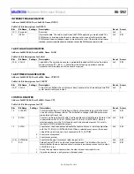
REGISTER DETAILS: GENERAL-PURPOSE TIMERS
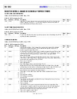
16-BIT SYNCHRONOUS LOAD VALUE REGISTERS
Address: 0x40000000, Reset: 0x0000, Name: GPT0_LOAD
Address: 0x40000400, Reset: 0x0000, Name: GPT1_LOAD
Address: 0x40000800, Reset: 0x0000, Name: GPT2_LOAD
Table 343. Bit Descriptions for GPT0_LOAD, GPT1_LOAD, GPT2_LOAD
Bits Bit
Name
Settings
Description
Reset Access
[15:0] LOAD
Load Value. The up or down counter is periodically loaded with this value if periodic
mode is selected (GPTx_CTL, Bit 3 = 1). This bit writes during up or down counter
timeout events that are delayed until the event passes.
0x0000 R/W
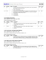
16-BIT TIMER SYNCHRONOUS VALUE REGISTERS
Address: 0x40000004, Reset: 0x0000, Name: GPT0_CURCNT
Address: 0x40000404, Reset: 0x0000, Name: GPT1_CURCNT
Address: 0x40000804, Reset: 0x0000, Name: GPT2_CURCNT
Table 344. Bit Descriptions for GPT0_CURCNT, GPT1_CURCNT, GPT2_CURCNT
Bits Bit
Name
Settings
Description
Reset Access
[15:0] VALUE
Current Count. Reflects the current up or down counter value. Value delayed by two
PCLK cycles due to clock synchronizers.
0x0000 R
CONTROL REGISTERS
Address: 0x40000008, Reset: 0x000A, Name: GPT0_CTL
Address: 0x40000408, Reset: 0x000A, Name: GPT1_CTL
Address: 0x40000808, Reset: 0x000A, Name: GPT2_CTL
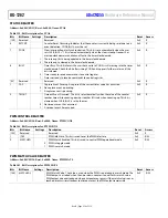
Table 345. Bit Descriptions for GPT0_CTL, GPT1_CTL, GPT2_CTL
Bits Bit
Name Settings
Description
Reset
Access
15 SYNCBYP
Synchronization Bypass. Used to bypass the synchronization logic within the block. Use
only when both the general-purpose timer and the CPU are clocked from the same source.
0x0 R/W
14 Reserved
Reserved.
0x0 R
13 EVTEN
Event Select. Used to enable and to disable the capture of events. This bit is used in
conjunction with the event select range. When a selected event occurs, the current
value of the up or down counter is captured in GPTx_CAPTURE.
0x0 R/W
0
Events are not captured.
1
Events are captured.
[12:8]
EVTRANGE
Event Select Range. Timer event select range (0 to 31).
0x0
R/W
7 RLD
Reload Control. This bit is only used for periodic mode. This bit allows the user to select
whether the up or down counter is reset only on a timeout event or also when CLRINT,
Bit 0 is set.
0x0 R/W
0
Up or down counter is only reset on a timeout event.
1
Resets the up down counter when CLRINT, Bit 0 is set.
[6:5]
CLK
Clock Select. Used to select a timer clock from the four available clock sources.
0x0
R/W
00
PCLK.
01
High frequency oscillator. 26 MHz high frequency oscillator.
10
Low frequency oscillator. 32 kHz low frequency oscillator.
11
Reserved.
4 EN
Timer Enable. Used to enable and to disable the timer. Clearing this bit resets the
timer, including the GPTx_CURCNT register.
0x0 R/W
0
Timer is disabled. Default.
1
Timer is enabled.


