DVI Input & Output Boards
110
Enova Digital Media Switchers - Hardware Reference Manual
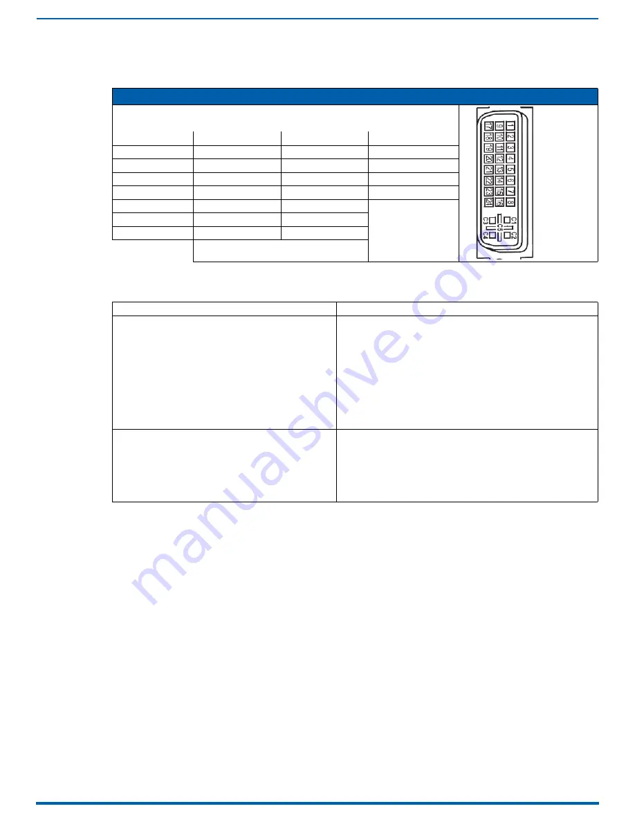
DVI Pinout
Pinout information for the DVI-I connector on the DVI Input and Output Boards is listed in the table below:
Troubleshooting Video
The following troubleshooting tips both involve signal support from or to third-party devices:
DVI-I Pinout
1. Data 2-
9. Data 1-
17. Data 0-
C1. No connect
2. Data 2+
10. Data 1+
18. Data 0+
C2. No connect
3. Ground
11. Ground
19. Ground
C3. No connect
4. No connect
12. No connect
20. No connect
C4. No connect
5. No connect
13. No connect
21. No connect
C5. No connect
6. DDC-CLK
14. +5 V
*
22. Ground
7. DDC-Data
15. Ground
23. CLK+
8. No connect
16. Hot-Detect
24. CLK-
*
DVI output pin 14 (+5 VDC out) supplies 50 mA
per each of the four output connectors.
Problem
Solution
The DVI Input Board does not pass video through the
enclosure to a connected display.
The likely cause is that the signal is from an incorrectly
formatted source (e.g., VTC, wall processor with combined
output, or signal generator) and the Enova DGX firmware
(v1.6.4.1 and later) includes a background measurement
process for detecting valid video. If the incoming signal fails to
meet the Enova DGX criteria, it will not pass the signal.
Turn off the firmware’s background checks and run video without them:
• Install Enova DGX firmware v3.0.0.4 or later.
• Use the DGX_SHELL command set
BCPUx_bg_vsync_disabled=ON
(where x is the input board slot number) to disable the background
check (affects the entire input board). The command
BCPUx_bg_vsync_disabled=OFF
enables the background check.
The video will route through the Enova DGX from source to destination as
soon as the command is sent.
The board’s setting persists through power cycles and will persist the
setting when removed from the enclosure and added to another, while
a new board replacing the old board will be set to OFF (default).
Note: A complete list of the DGX_SHELL targets, BCPUx, is in the "Product
to Board Slot Correspondence" table on page 275.
Video from the DVI Output Board to a third-party device (e.g.,
VTC, wall processor) does not display or displays with flickers.
The problem is usually caused by destination devices with
weak or no input equalization (i.e., the video stream from the
output board attempts to lock onto the destination; however,
the destination is unable to provide a stable connection). This
is made worse when signals are passed through low-quality or
long-distance cable runs.
Use one or more of the following work-around suggestions to avoid the
issue:
• Replace low quality cables with higher quality cables.
• Use shorter cable runs.
• Install an EDID emulator, an HDMI equalizer/repeater, or another
device that rebuilds/re-clocks the signal.
You will know the problem is resolved when the video signal appears on
the display device without flickering.


