instruction manual
Custom Panel Interfaces
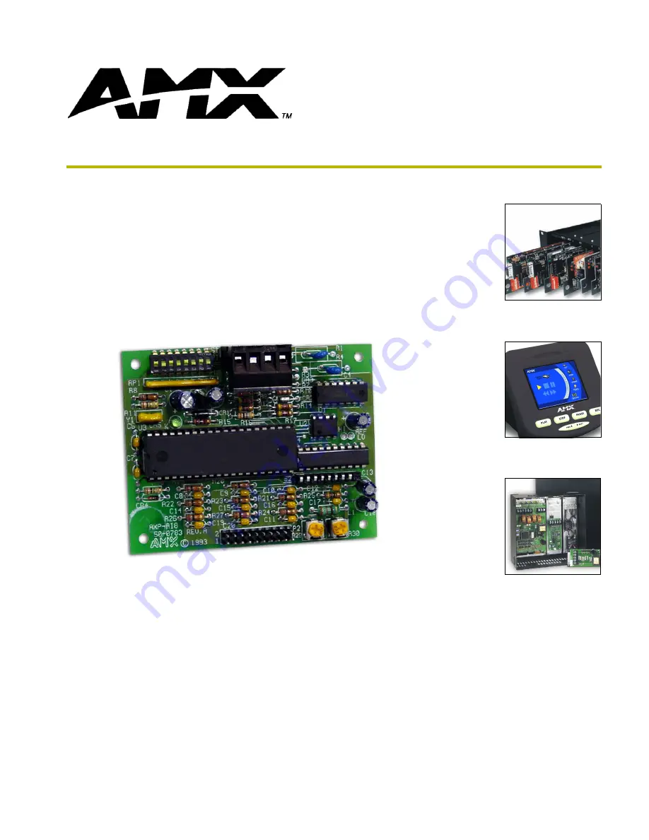
AXP-AI8
Eight-Channel Analog Input Interface Board
Страница 1: ...instruction manual Custom Panel Interfaces AXP AI8 Eight Channel Analog Input Interface Board...
Страница 2: ...liability applies whether damages are sought or a claim is made under this warranty or as a tort claim including negligence and strict product liability a contract claim or any other claim This limita...
Страница 3: ...s 1 Dimensions and Descriptions 2 Installation 3 Configuring Switches 3 Setting the Device DIP Switch 3 Setting the input SIP switch 3 Setting the joystick range POTs 3 Wiring 4 20 Pin Header 4 AXlink...
Страница 4: ...ii AXP AI8 Eight Channel Analog Interface Board Table of Contents...
Страница 5: ...wer or the controller is not functioning properly One blink per second Normal operation Device numbers match the programmed device numbers in the Axcess program Cables 3 feet 91 4 cm of ribbon cable w...
Страница 6: ...Inch mm Item Description A 0 20 5 10 G 20 Pin Header 025 inch 6 mm square pins 1 inch 2 4 mm typical spacing B 3 50 88 90 H 125 inch 3 2 mm mounting holes for 4 40 3 mm screws C 3 10 78 70 D 2 75 69 9...
Страница 7: ...ed inputs For example switch position 1 corresponds to input 1 In the illustration above switches 1 and 8 are ON designating that input 1 and 8 are disabled The default setting is all switch positions...
Страница 8: ...screws clockwise to secure the fit Do not over torque the screw doing so can bend the seating pin and damage the connector FIG 5 shows the wiring configuration for AXlink cables Be sure that the boar...
Страница 9: ...control system Master port 2 Select Diagnostics and Watch Variable enter the name of the variable for Input 1 Note the value of the variable when the joystick is in the center position Note the value...
Страница 10: ...T 13 56 05 FILE_LAST_MODIFIED_ON 04 25 2001 AT 16 59 10 Levels Level Function 1 Voltage output channel 1 and joystick slider control 0 255 5 Voltage input channel 1 0 255 2 Voltage output channel 2 an...
Страница 11: ...hese array elements below Or setup the variables without an array IN1 2 VARIABLES IN WHICH TO STORE IN2 2 ANALOG INPUT VALUES LEVELS IN3 2 IN4 2 IN5 2 IN6 2 IN7 2 IN8 2 IN1 VARIABLES IN WHICH TO STORE...
Страница 12: ...CREATE_LEVEL AI8 4 IN4 1 ANALOG VALUE LEVEL CREATE_LEVEL AI8 5 IN5 1 CREATE_LEVEL AI8 6 IN6 1 CREATE_LEVEL AI8 7 IN7 1 CREATE_LEVEL AI8 8 IN8 1 THE ACTUAL PROGRAM GOES BELOW DEFINE_PROGRAM IF IN1 1 5...
Страница 13: ...___________________ Date _____________________________________________ PO __________________________________________ SO _____________________________________________ Serial ___________________________...
Страница 14: ...e richardson TX 75082 USA 469 624 8000 800 222 0193 fax 469 624 7153 technical support 800 932 6993 038 004 1034 12 03 2003 AMX Corporation All rights reserved AMX the AMX logo the building icon the h...